Traffic load
Traffic load panel
The panel Traffic load contains only the Traffic load tool.
![]()
Traffic load tool
Use the Traffic load tool to apply specialized load patterns for road and railway bridges.
The tool helps you determine the most unfavorable load system and its position to road and railway bridges according to [G1]EN 1991-2. Traffic load patterns are objects associated with the Moving loads. A new traffic load creates one or more new Moving loads with a unit load, and with different Load cases.
![]()
When you select the Traffic load tool, a new tool palette opens.

Main tools on the tool palette
- Define – create new traffic load patterns on selected regions or lines
- Properties – check or edit parameters of existing traffic load patterns. Opens the Default settings dialogue for the selected elements
- Wizard – create a new traffic load pattern based on an existing one. The tool opens the Default settings dialogue with the same settings as the selected existing load pattern and creates the new load on the same physical location
- Mass generation – define multiple traffic loads automatically based on a selected prototype and load group (read below in more detail)
- Default settings – set default parameters for load type, geometry, and calculation options (read below in more detail)
If some critical settings are not filled into the Default settings dialogue (for example, the vehicle is not selected), then Define function will open Default settings dialogue after defining the path.
Load type
Available when the Define tool is selected.
- Road vehicle – for defining road traffic load models
- Train – for defining railway traffic load models
Definition methods
Depending on the selected Load type, different definition methods are available.
Road vehicle
- Simple line model – define a simplified line-based road traffic load along a straight or curved path
- Carriageway – define a complex carriageway region with one or several lanes. The surface load will be generated automatically based on the carriageway geometry
Train
- Simple line model – define a single-track railway traffic load along a straight or curved line
- Railway – define multiple railway lines or curved tracks with superelevation and variable geometry
To read about Moving loads see the topic:
User interface ➔ Tab menus ➔ Loads ➔ Panel Macro ➔ Moving load
Mass generation
Use the Mass generation tool to automatically create multiple traffic load patterns at once.
This function is useful when several load models or result components need to be generated in a systematic way.
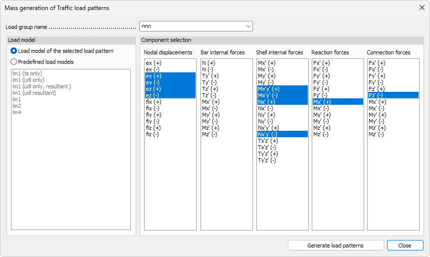
- Load group name – use the drop-down list to select the Load group in which the new traffic load patterns will be generated. You can write a new name to generate new group.
Load model
- Load model of the selected load pattern – generates new load patterns using the same load model as the currently selected pattern.
- Predefined load models – allows you to choose different load models than the currently selected pattern from the predefined Eurocode-based load models.
Component selection
Select which internal force or displacement components will be used to generate the load patterns.
The available categories are:
- Nodal displacements – translational and rotational displacements (ex, ey, ez, fix, fiy, fiz)
- Bar internal forces – axial, shear and moment components (N, Ty, Tz, My, Mz, Tz’, etc.)
- Shell internal forces – membrane and bending components (Nx, Ny, Nxy, Mx, My, Mxy, Txz, Tyz)
- Reaction forces – support reactions (Fx, Fy, Fz, Mx, My, Mz)
- Connection forces – connection interface forces (Fx, Fy, Fz, Mx, My, Mz)
- Generate load patterns – use the button to create all load patterns based on the selected load model and components in the chosen load group.
Default settings dialogue
When you press the Default settings button, a dialogue window opens.
The dialogue has five tabs: General, Load model, Load modifier, Lane alignments / Railways, and Calculation options.
The available options are slightly different depending on whether the selected load type is Road vehicle or Train.
General tab
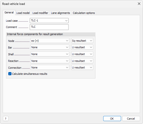
The General tab defines the basic data and result components for the traffic load pattern.
- Load case – use the drop-down list to select or create the load case where the traffic load will be stored.
- Comment – enter an optional comment or label to identify the load pattern in lists and documentation.
Internal force components for result generation
Select which internal force or displacement components will be used during result generation.
- Node – select the displacement or rotation component at nodal points (for example ez (+)).
- Bar – select internal force components in bar elements (for example N, My, Mz).
- Shell – select internal force components in shell elements (for example Nx, My, Mxy).
- Reaction – select support reaction components (for example Fx, Mz).
- Connection – select connection force components (for example Fx, Fy, Mz).
The limit state result set drop-down menu contains:
- U clone
- Sq clone
- Sf clone
- Sc clone
- U resultset
- Sq resultset
- Sf resultset
- Sc resultset
- U/Sq/Sf/Sc
- clone - it calculates the selected limit state and all results will be cloned to the others.
- resultset - it calculates the dominant load system by the selected limit state then calculate all results individually by this load system.
- U/Sq/Sf/Sc - all results will be calculated individually by all limit states.
- Calculate simultaneous results – when checked, the program calculates simultaneous results for the selected components.
- ? – info button opens the user manual to read more about the Traffic load tool
Load model tab
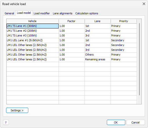
The Load model tab defines the vehicles, lane arrangement, and load distribution used in the traffic load pattern.
Each row in the table represents one vehicle or surface load acting in a specific lane/track.
- Vehicle – use the drop-down menu to select a vehicle from a specific traffic vehicle database.
- Edit library… – special entry in the Vehicle drop-down menu. Opens a dedicated window where you can add, rename, or modify vehicles (read below in more detail)
- Factor – load multiplier applied to the selected vehicle
- Lane/Track – the lane/track number or region where the vehicle acts. Options here are: 1st, 2nd, 3rd, Others and Remaining areas
- Priority – defines whether the lane is Primary, Secondary or Tertiary. Primary lanes are filled first when the load system is generated
You can remove vehicles from the table with delete button.
Settings >
When you click on the Settings button in the bottom, a new menu opens.

- Save – save the settings with a name to use later
- Load – load a previously saved setting
- Save as default – save settings that are automatically used as default next time in this dialogue
- Load defaults – load the default settings to overwrite current settings
- list of vehicles - depending on the selected load pattern a list of vehicles is displayed in the Settings > menu to speed up the setup.
Using any vehicle from the Settings > list will overwrite the data on the table, but you can still cancel out of the dialogue.
Load modifier tab
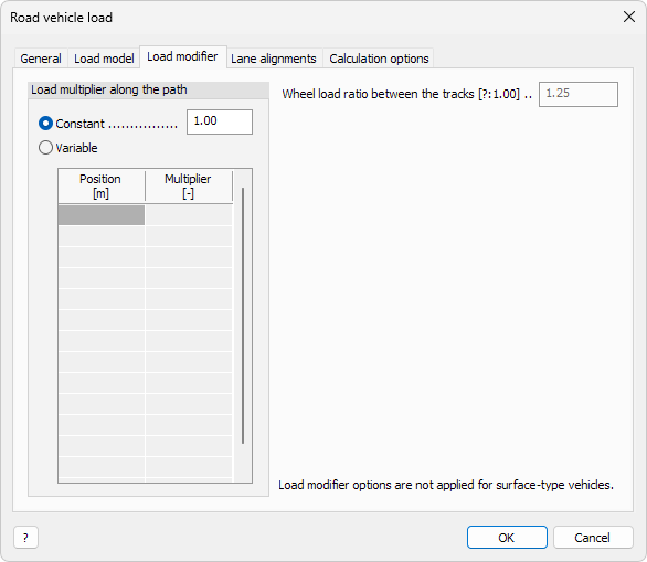
The Load modifier tab defines the load multipliers that modify the intensity of the traffic loads along their path. These modifiers can be used to apply national annex factors or dynamic amplification coefficients.
Load multiplier along the path
-
Constant – apply a single multiplier to the entire load path. Enter the value in the numeric field next to it
-
Variable – define different multiplier values at specific positions along the path. Use the table below to set each position and corresponding multiplier value
-
Position – distance along the path from the starting point of the vehicle
-
Multiplier – load multiplier factor applied at that position
- Wheel load ratio between the tracks – numeric field defining the ratio of wheel loads between left and right tracks. The value expresses the imbalance between the two sides of the vehicle. qv2/qv1; Qv2/Qv1 ≤ 1,25 according to [G1]EN 1991-2 6.3.5 (1)
Load modifier options are not applied for surface-type vehicles.
Lane alignments / Railways tab
The Lane alignments / Railways tab defines the geometric arrangement of lanes or tracks depending on the selected load type.
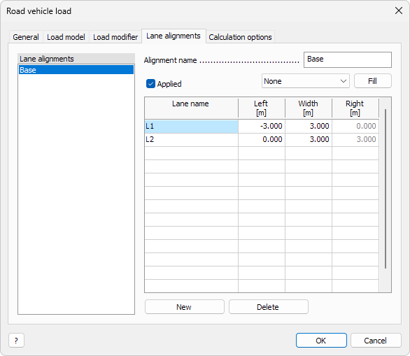
Road vehicle load
The Lane alignments tab defines the position and width of each traffic lane used in the road vehicle load model. You can create multiple lane alignment sets to represent different traffic configurations.
- Lane alignments list – shows all defined alignment sets. Selecting one displays its parameters on the right side of the window
- Alignment name – user-defined name for the selected lane alignment set
- Applied – tick the checkbox to activate the selected alignment for calculation
- drop-down list next to Filled – only available for Carriageway type (not available for Simple line model). Select how to align the automatically generated lanes on the Carriageway geometry
- Fill – automatically generate lane positions according to the current Carriageway geometry and selected alignment
Each row in the table represents a single lane and its geometric boundaries.
- Lane name – identifier of the lane
- Left – left boundary position of the lane relative to the reference axis
- Width – width of the lane
- Right – right boundary position of the lane relative to the reference axis
- New – add a new lane alignment set
- Delete – remove the selected lane alignment set
New and Delete work on the lane alignment sets on the left hand table. You can add new lanes to the right hand table by writing the Lane name. You can remove lanes by using DELETE button on keyboard.
Train load
For train-type loads, the tab is renamed to Railways. The Railways tab contains a single parameter that is available only for Simple line model railways:
- No. of railways – numeric field where you can enter the number of railway tracks in the load model
Calculation options tab
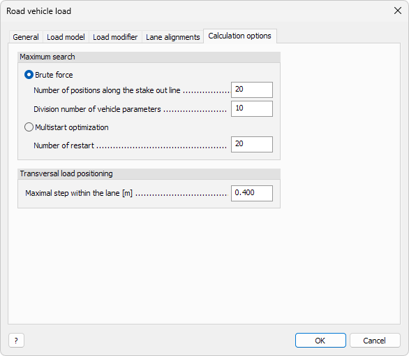
The Calculation options tab defines how the program searches for the most unfavorable load position and how the vehicle is positioned transversally within the lanes.
Maximum search
Select the method used for finding the critical load position.
-
Brute force – evaluates all possible discrete positions of the vehicle along the path.
- Number of positions along the stake out line – defines how many discrete positions are checked along the vehicle’s path.
- Division number of vehicle parameters – defines the resolution of the parameter variation (for example axle distances or load distribution factors).
-
Multistart optimization – uses a numerical optimization method to find the maximum load effect continuously.
- Number of restart – number of random initial positions used for starting the optimization process.
Use Brute force for smaller or simpler models to ensure fully deterministic results.
Use Multistart optimization for large or complex models to reduce calculation time when small variations in load position have minor influence.
Transversal load positioning
- Maximal step within the lane [m] – defines the maximum lateral increment between consecutive vehicle positions within the same lane. A smaller value increases accuracy but also the calculation time.
Vehicle library
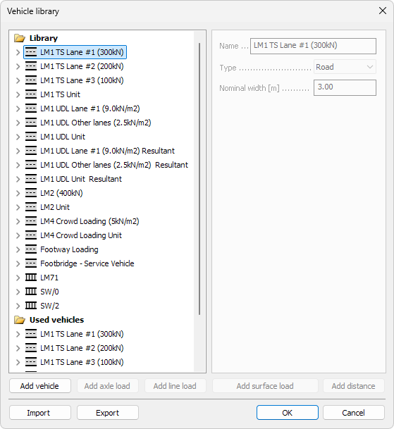
The Vehicle library dialogue defines and manages the list of available vehicles used in traffic load models.
You can edit existing vehicles, add new ones, or import and export complete libraries.
Library list
- The list on the left shows all predefined vehicle types organized in groups.
- Vehicles can include axle loads, line loads, surface loads, and their combinations.
- The folder Used vehicles contains the vehicles that are currently assigned to the active load model.
Import / Export
- Import – load a previously saved vehicle library file. Entries with matching names will be ignored, keeping the local definitions
- Export – save the current vehicle library to an external file
Add vehicle

Use the Add vehicle button to create a new vehicle entry in the library.
- Name – unique name of the new vehicle
- Type – choose from Road or Rail
- Nominal width – width of the vehicle, used in lane or track generation
Add axle load

Use the Add axle load button to define an axle-type load for the selected vehicle.
- Qk – characteristic concentrated load on the axle
- Number of wheels – number of wheels on the axle
- Wheel size in longitudinal direction – length of the wheel contact area
- Wheel size in transversal direction – width of the wheel contact area
- Wheel spacing – center-to-center distance between wheels
Add line load

Use the Add line load button to define distributed loads acting along a line.
- qk – characteristic line load intensity
- Minimum length – minimum possible loaded length
- Maximum length – maximum possible loaded length
- Allowed discontinuity – checkbox to enable load gaps along the line
- Number of wheels – number of wheel contact points on the line
- Wheel size in transversal direction – width of each wheel contact area
- Wheel spacing – distance between adjacent wheels
Add surface load
![]()
Use the Add surface load button to define uniform or patch loads over a surface area.
- q – characteristic surface load intensity
Surface loads can be discontinuous and will be applied in the unfavorable places.
It is only allowed to use surface loads uniquely as a Vehicle part.
Load modifier options are not applied for surface loads.
Add distance

Use the Add distance button to define the longitudinal spacing between load components.
- Minimum length – shortest allowed distance between components
- Maximum length – longest allowed distance between components
Additional information to read
As this article focuses on the user interface, the other parts and background information function is further described in this external article: