7th degree of freedom
7th degree of freedom
FEM-Design 25 introduces a brand-new analytical model element: the 7DoF warping bar, available for beams and columns.

This new “7th degree of freedom” finite bar element captures restrained warping deformation, allowing engineers to perform economical yet accurate design using simple beam elements instead of complex shell or solid models.
Theory
For detailed information about the theory, please read the theory and verification examples document:
Key characteristics
The element considers primary and secondary warping torsion effects in a first-order manner.
The 7DoF bar is applicable not only to thin-walled open sections but also to general cross-sections and multiple material types – including steel, concrete and timber – enabling accurate torsional and stability analysis.
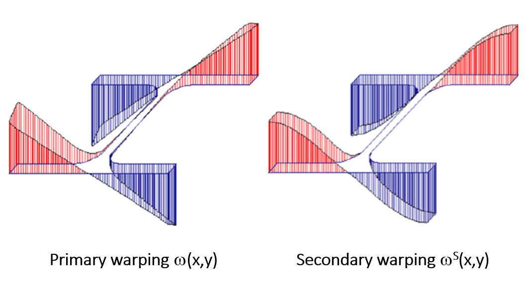
The element employs a higher-order secondary warping function that satisfies the equilibrium of warping shear stresses along the perimeter, ensuring a more realistic torsional behaviour than a primary warping function alone, as illustrated in the figure below.
As a result, warping contributes not only to the normal stresses but also to the shear stresses in a coupled manner, as demonstrated by the equations below, where the interaction between the transverse shear forces and the warping moment can be observed.
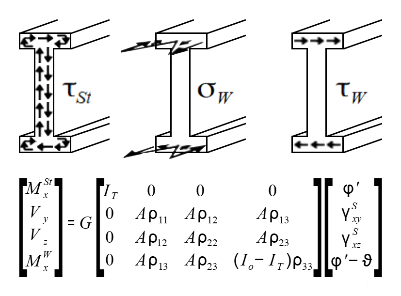
The required ρ shear correction factors are calculated automatically by the FEM-Design Section Editor.

Limitations
Currently, there are some limitations to the 7DoF warping:
- The 7DoF warping bar is currently not available for tapered (variable cross-section) members.
- Plasticity and 7DoF behaviour cannot be applied simultaneously to the same bar element.
- The 7DoF analysis calculations are not yet considered in the design modules.
Stability analysis capabilities
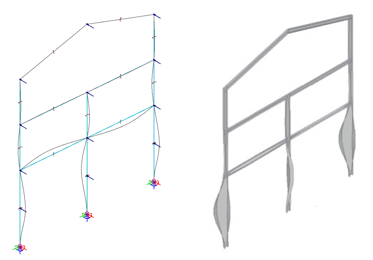
The element accurately captures complex lateral–torsional buckling modes of beams and entire frame structures.
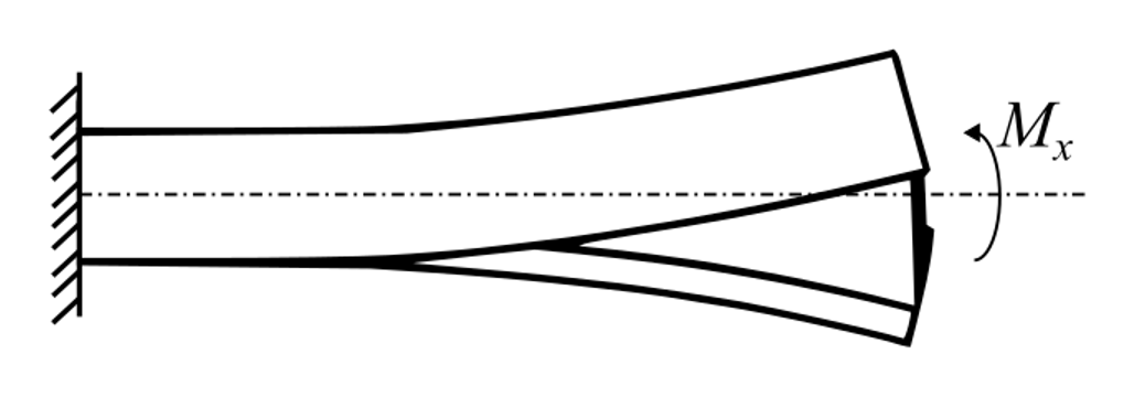
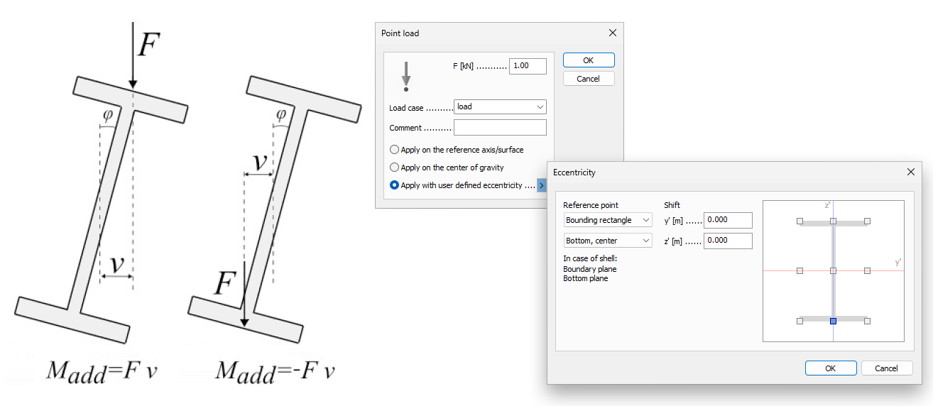
It accounts for the destabilising effect of eccentric loads, ensuring accurate Mcritical predictions.
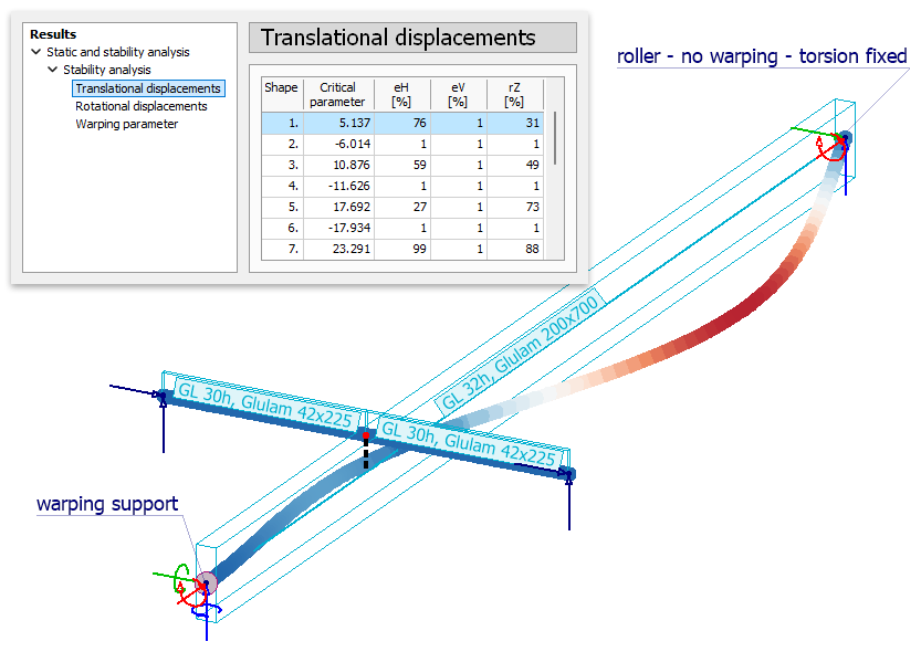
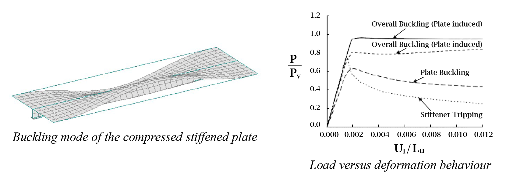
Arbitrary reference axes can be defined, making the element ideal for modelling stiffening ribs of plates.
This approach enables the analysis of “tipping-type” stability loss in stiffened plate structures – one of the most dangerous failure modes due to its significant stiffness reduction.
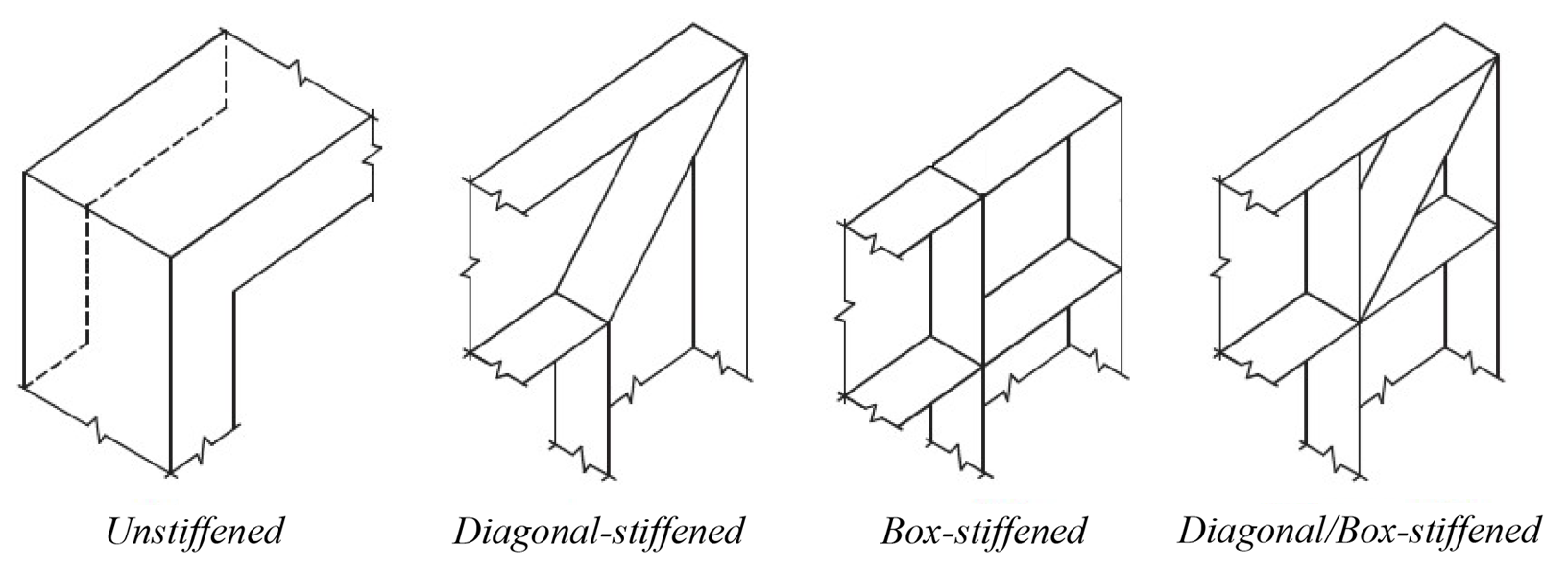
Connection modelling
To model frame structures accurately, it is easy to set up simple beam connections such as the following:
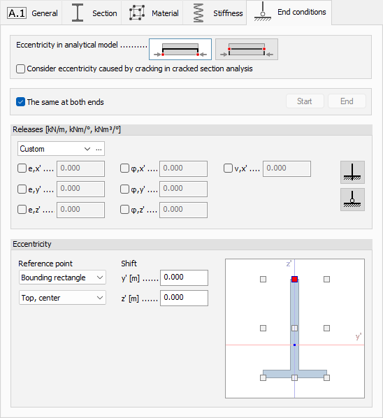
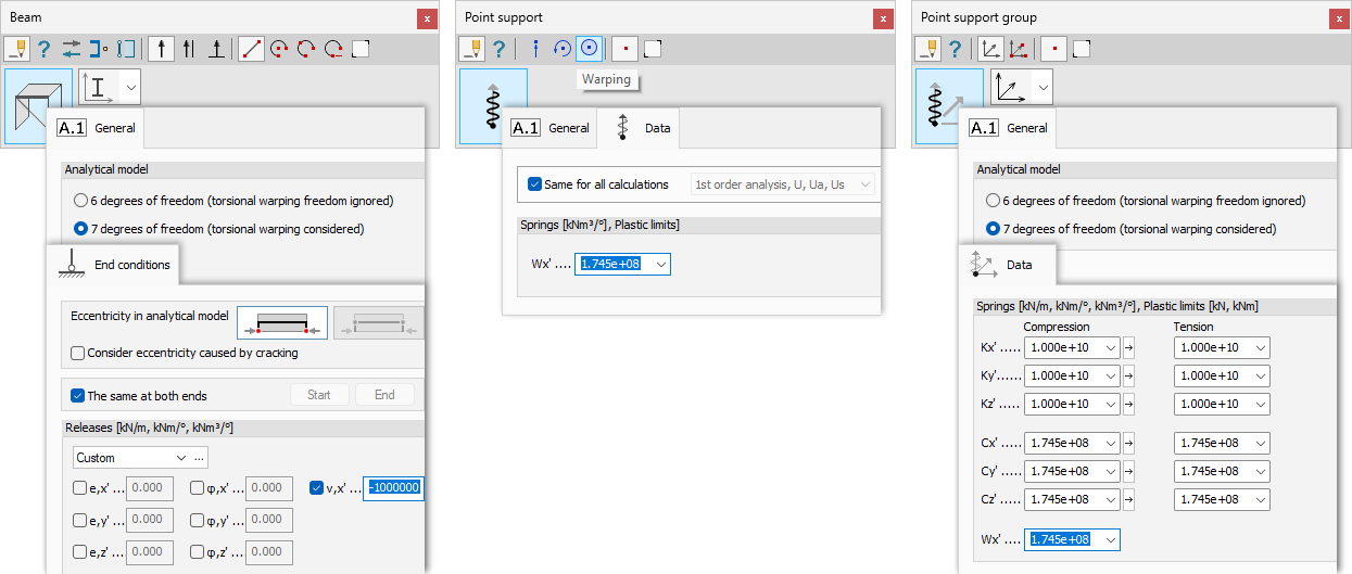
Using the End conditions settings and the new Warping support type, users can adjust warping transfer to define the required connection behaviour with just a few clicks.
New stress resultants
The 7DoF beam introduces a new stress resultant, the Bimoment [kNm²], and decomposes the torsional moment into St. Venant and warping-induced components.
This enables direct application of the dimensioning formulas in second-generation Eurocode 3, clause 5.1.2 (4), which require a 7DoF beam model for torsion-loaded steel members.
The contribution of each stress resultant to the various stress components can also be checked, meaning Eurocode design values such as τSt and τw can be obtained easily.
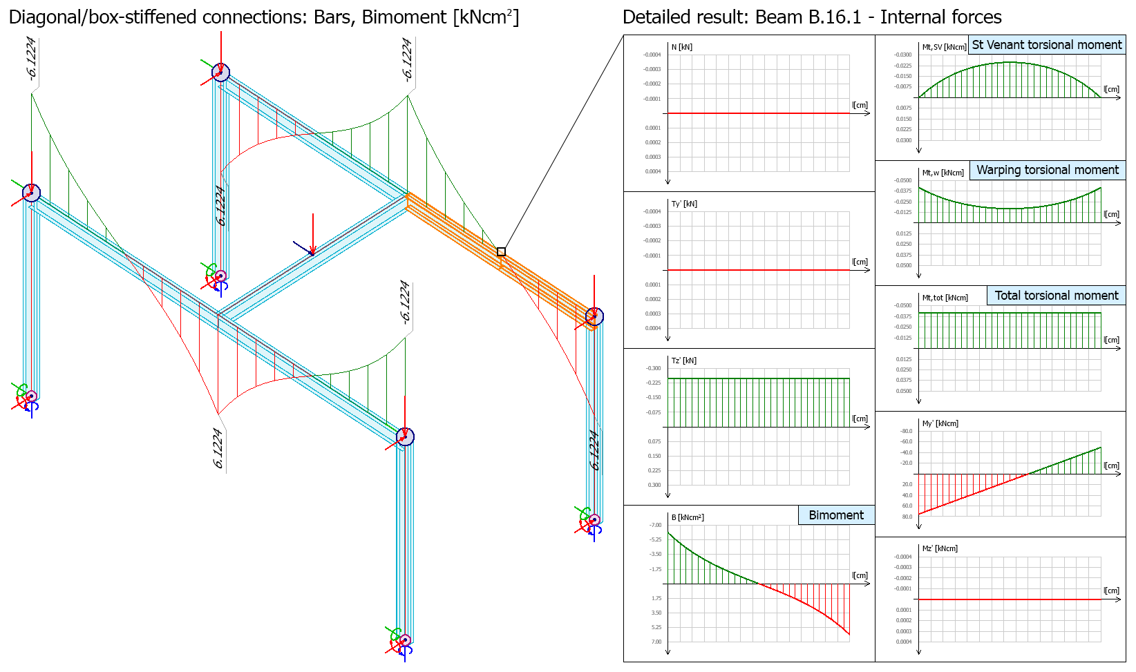
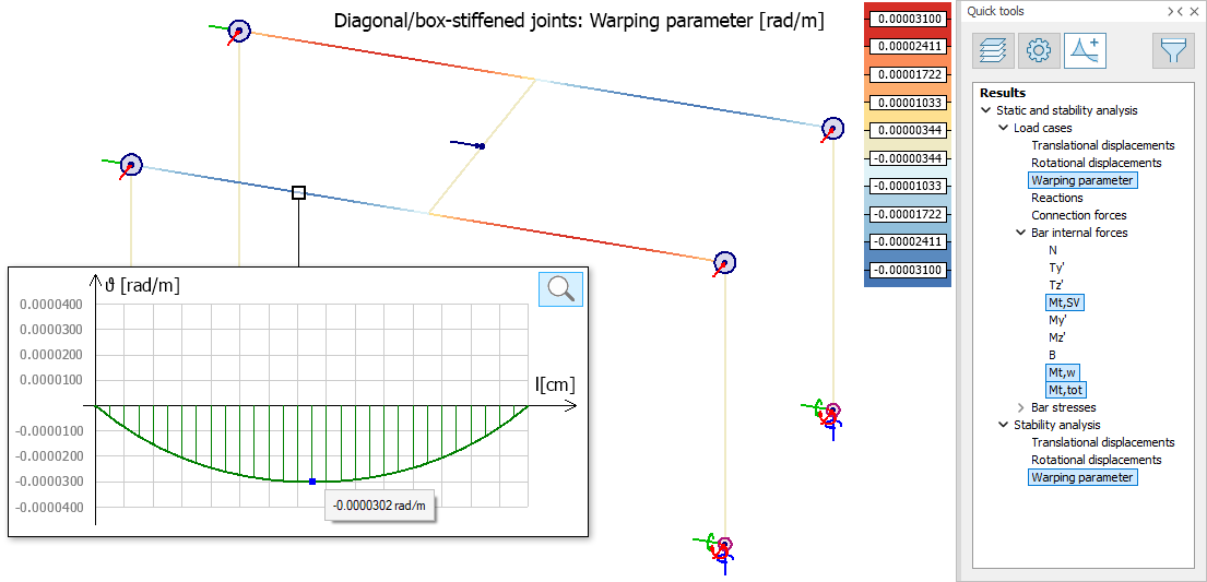
The new bar results – including the axial warping parameter (representing the magnitude of the warping deformation as introduced by Kollbrunner) – are also available in 3D model windows.
Performance and convergence
The new element uses a homogeneous interpolation technique, providing excellent numerical performance. As a result:
- even very few elements, for example one per span in a multi-span beam, can reproduce the complex hyperbolic distribution of bimoments and warping moments
- no local mesh refinement is needed to identify critical cross-sections
- the method shows superior convergence, allowing fast calculations and quick iteration between design variants compared to complex shell models