IFC enhanced
IFC enhanced
In today’s BIM-driven design workflows, open data exchange is essential for efficient multidisciplinary collaboration. FEM-Design 25 continues to strengthen its commitment to OPEN BIM, ensuring that structural engineers can seamlessly cooperate with architects, infrastructure designers, MEP engineers and detailers – regardless of which software tools they use.
IFC Import
Support for IFC 4.3
FEM-Design aims to continually support the latest IFC standards. IFC 4.3 brings major improvements by extending the format beyond traditional building models to large-scale infrastructure projects, such as roads, railways, waterways and bridges.
Although linear infrastructure alignment elements (e.g. IfcAlignment, IfcRoad, IfcRailway) are not intended for import in FEM-Design, the associated structural components – such as bridge structures – need to be fully supported.
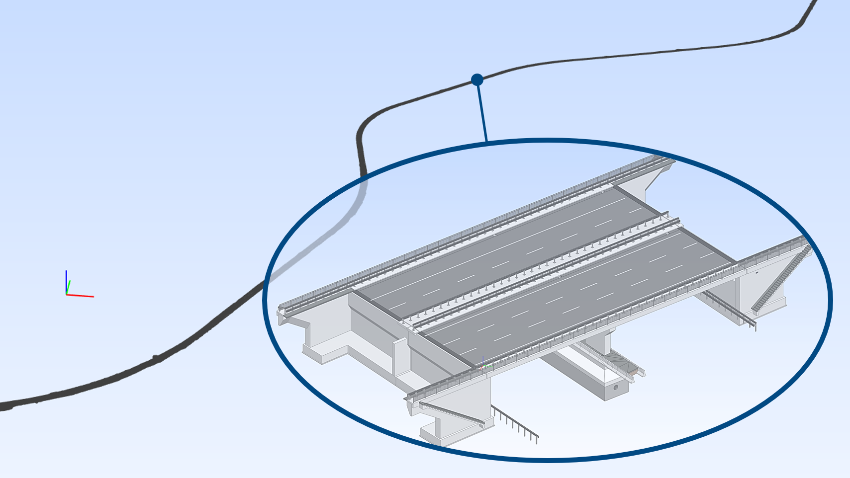
FEM-Design 25 ensures that these IFC 4.3 structural elements are correctly imported either as editable analytical elements or as reference objects, supporting engineers participating in infrastructure-related projects. Naturally, building structures exported in IFC 4.3 format are fully supported as well.
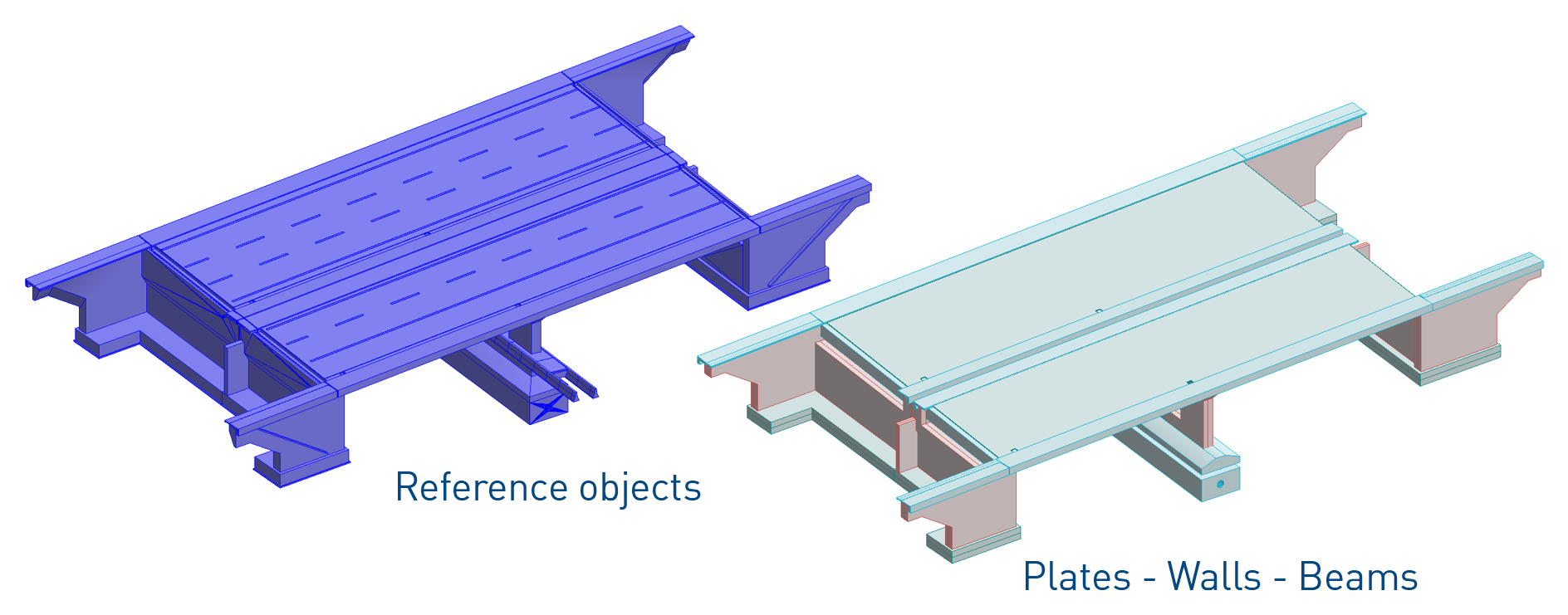
If elements are imported as reference objects, they can later be manually converted – object by object – into the appropriate analytical element type with the correct material assignment using the target element’s Convert tool, with a single click.
Import of new IFC entities
New IFC element entities can be imported to FEM-Design.
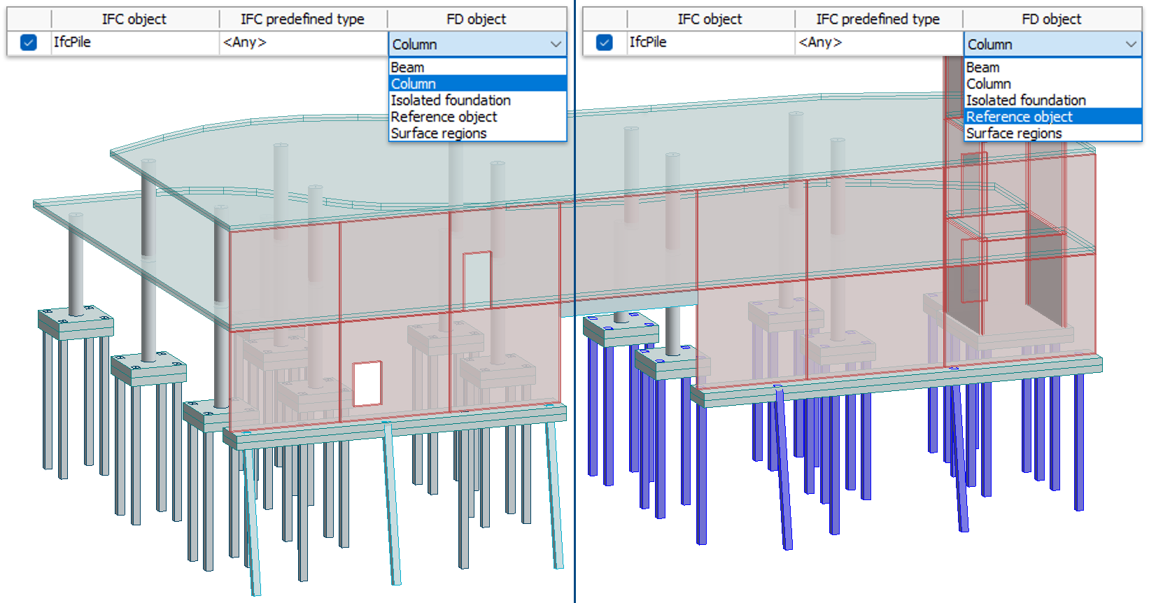
IfcPile
FEM-Design 25 can now import IfcPile entities. Upon import, piles may be converted into Columns, Beams or Reference objects, depending on the user's choice and the intended analytical role.
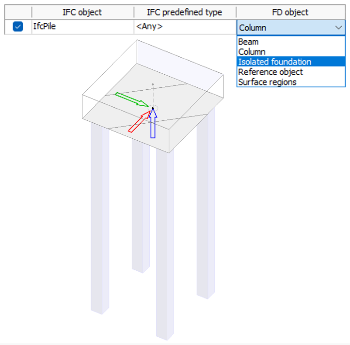
Pile caps can also be imported as FEM-Design Isolated foundation objects.
IfcPile objects cannot be imported directly as native FEM-Design Pile elements, because pile creation in FEM-Design requires initial soil spring data derived from an existing soil model. However, once a Soil model has been defined, the imported column, beam or reference objects can be converted into a native Pile element with a single click.
IfcSite geometry and IfcGeographicElement
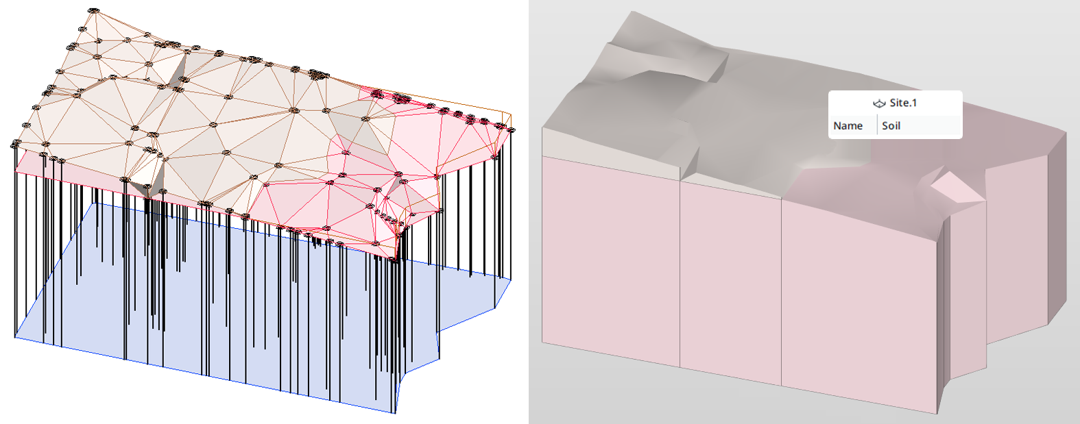
Some IFC models contain terrain geometry not only for visualisation, but to represent the actual upper soil surface used in geotechnical modelling. This geometry may come from IfcSite surface or solid representations, or from IfcGeographicElement entities, commonly exported from Revit Toposolid objects since IFC4.
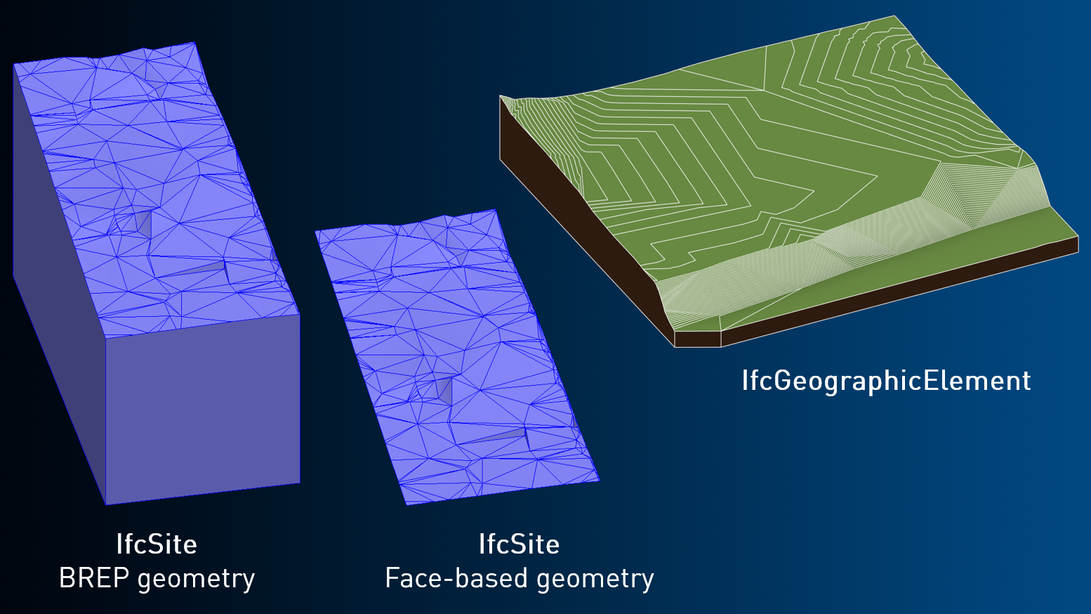
In FEM-Design 25, these terrain geometries are imported as reference objects – either as solids or as connected surface regions.
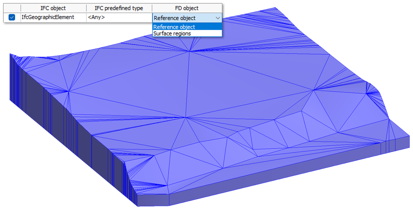
They can then be used to generate the upper surface of the Soil model directly from IFC using the new 3D shape function, removing the need to manually define elevation points or place boreholes. Other soil parameters, such as depth, strata and groundwater levels, automatically follow the project’s default Soil settings.
The new Soil converter function can be applied not only to terrain geometries imported from IFC, but also to continuously connected regions and solid objects drawn directly in FEM-Design.
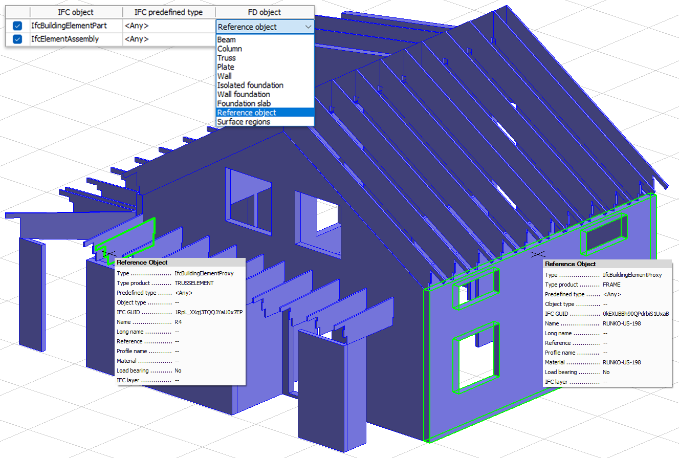
IfcElementAssembly and IfcBuildingElementPart
Such entity types may appear in BIM models where elements are not explicitly classified by type or function, or where they represent low-level items in the model hierarchy, for example created through element subdivision.
To ensure that FEM-Design 25 can extract potential structural components even from models structured this way, these entities can be imported as reference objects, as surface-based geometry regions or as analytical elements of a selected type, such as Beam or Plate.
Editing of reference objects
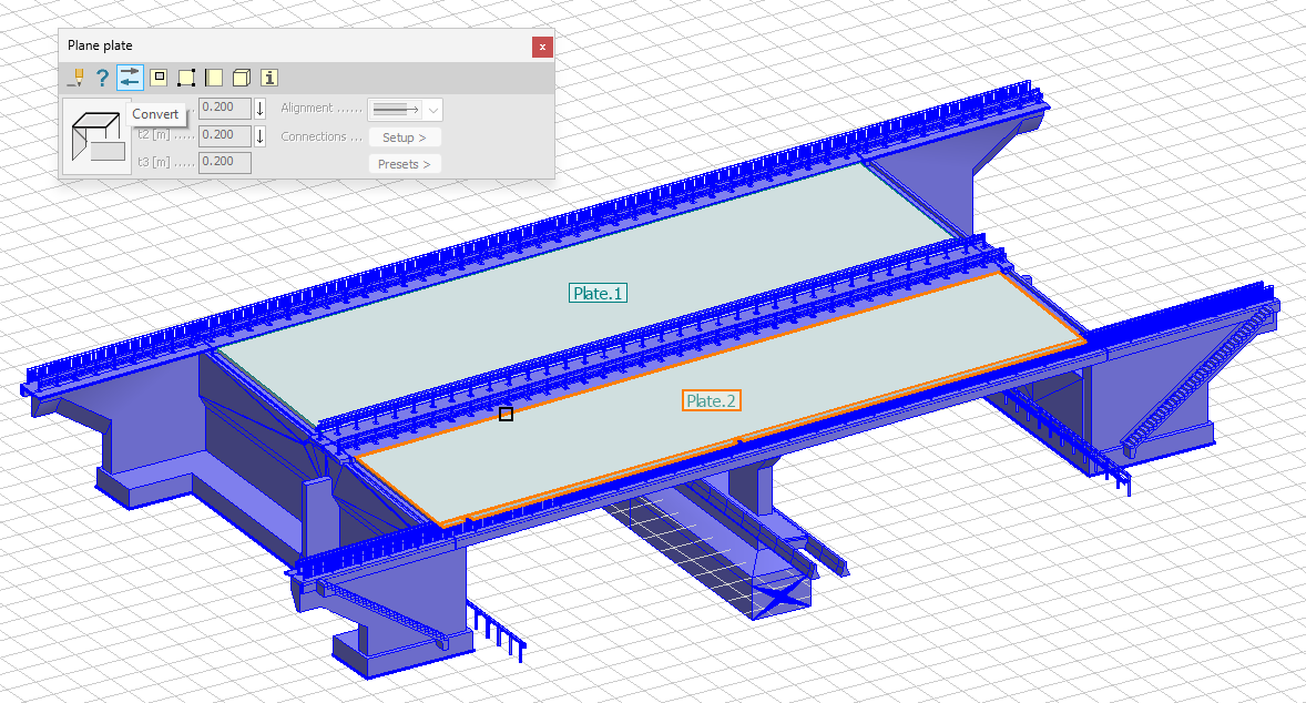
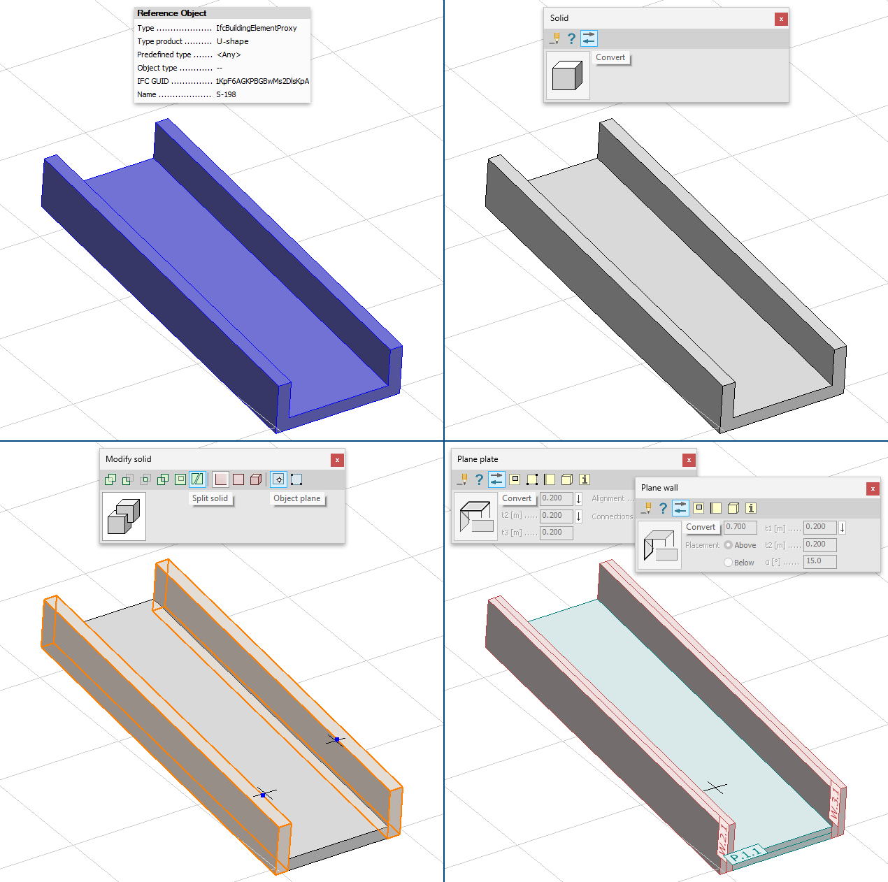
FEM-Design 25 enables editing of IFC-imported reference solids by converting them into FEM-Design drawing solids. Once converted, the geometry becomes editable – for example, it can be subdivided to separate shapes that correspond to multiple analytical members.
This is especially useful when a single IFC entity represents several structural elements, such as a U-shaped slab that must be split before converting it into plates or walls.
Conversion workflow:
- convert the imported reference object into a drawing solid using the new Convert tool of the Solid command
- modify or subdivide the solid geometry as needed
- convert each resulting part into the desired analytical element type
Analytical elements can also be converted into drawing solids if they should no longer participate in the analysis, while still remaining in the model as editable reference geometry. These solids can be reconverted into analytical elements at any time – the geometry is preserved, while all other properties follow the current Convert settings.
IFC model merge
FEM-Design 25 now supports merging multiple IFC files into a single project, enabling the following workflows:
- importing models by discipline, such as structure, MEP or spaces
- importing repetitive structural units, for example storey-by-storey IFC files
- adding new model parts to an existing FEM-Design project
- importing a new model version or alternative as a reference model alongside an analytical model created from a previous version, allowing the two to be visually distinguished
The Paste command now works for IFC files as well, allowing repeated or sequential IFC imports. Users can apply custom import settings for each file or reuse import templates, named presets that store material mappings, section mappings and object-type mappings.
If the same IFC model is imported multiple times, original element GUIDs are replaced with new ones to avoid duplication of unique identifiers.
IFC Export
It is essential that all designed structural members and auxiliary components can be exported reliably in IFC format for coordination, detailing and fabrication workflows, and BIM-based project delivery. FEM-Design 25 continues to expand its export capabilities to meet this expectation.
Exporting Soil models
The Soil model used in the analysis can now be exported to IFC as a geometric representation assigned to the project’s IfcSite entity.
Exporting model parts according to UCS
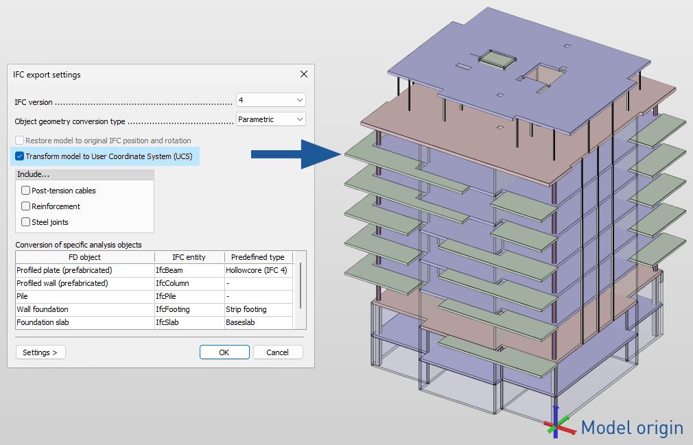
For large-scale projects, such as multi-building developments or industrial facilities, it is often necessary to export specific model parts using a custom coordinate system. FEM-Design 25 now allows exporting selected elements in the coordinate system defined by the user, the User Coordinate System (UCS), with a custom origin and axis orientation.
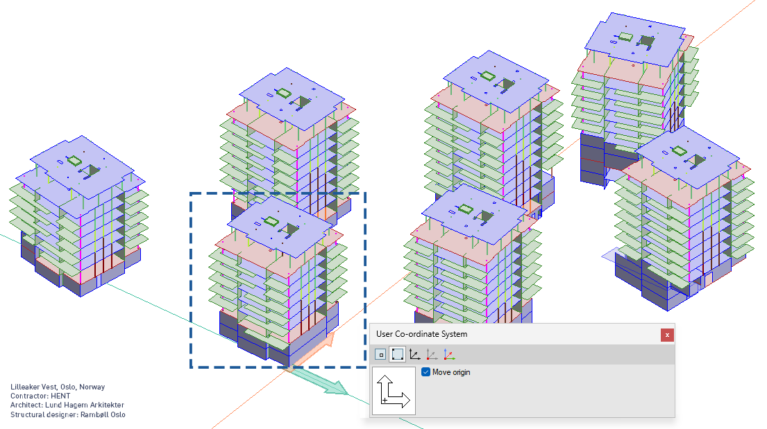
Export workflow:
- define a UCS at the required origin and orientation
- choose Export to IFC for selected elements, or use Save as to export the entire project
- enable the new Transform model to User Coordinate System (UCS) option in the IFC export settings