Bar End conditions
The Bar - End conditions dialogue controls releases, eccentricities, and end-specific settings for line elements.
Following tools provide this dialogue. Some use full dialogue, others use only reduced version:
- Beam
- Column
- Intermediate section
- Column corbel
- Pile
- Wall foundation
When you open the End conditions tab, the following (or similar) window appears.
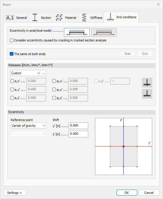
Eccentricity in analytical model
Two mutually exclusive options determine where end-releases are applied:
- End-releases applied at ends of theoretical axis – use when the bar connects directly to a shell or to another bar along its centre-line
- End-releases applied at centre of gravity (physical axis) – use when the joint is offset from the axis of the connected bar
- Consider eccentricity caused by cracking in cracked section analysis – include additional offset created by redistributed stresses
Same at both ends
- The same at both ends – when ticked, start and end share identical settings.
Untick to activate Start and End buttons and assign different releases and offsets per end
Releases
- Type – drop-down list of named release sets
- […] – the three-dot button next to the drop-down list opens a dedicated library modification window where you can add, rename, or modify release presets (read below for more detail)
Each degree of freedom has a checkbox and a numeric spring value (0 = free, large number = fixed):
| Translation | Rotation | Warping |
|---|---|---|
| e,x′ – axial | φ,x′ – torsion | v,x' – torsional warping |
| e,y′ – local y | φ,y′ – bending about y | - |
| e,z′ – local z | φ,z′ – bending about z | - |
Quick presets:
- Fixed – sets all components to rigid
- Hinged – releases only bending rotations φ,y′, φ,z′ and warping v,x', while keeping torsion and translations fixed
Eccentricity
Specify local offsets between the analytical line and the physical centroid:
Reference point
There are two drop-down menus for selecting where the offset shifts are measured from:
- Base point – select the base for the measurements. Available options are: Center of gravity, Shear center and Bounding rectangle
- Point on bounding rectangle – only available when Bounding rectangle is selected as the Base point. Select one of the nine reference points on the bounding rectangle as the base
Shift
The Shift values contain the offsets from the selected reference point.
- y′ – lateral offset
- z′ – vertical offset
Graphical snap
A miniature cross-section sketch shows key reference points (e.g., top-left corner, centroid). Click any point to auto-fill the y′ and z′ fields with its coordinates, ensuring quick and accurate placement.
If Bounding rectangle is selected as the reference point, then the graphical snapping window allows to change the Point on bounding rectangle, but does not change the Shift offset values.
Edit library dialogue
Clicking the […] button next to the Type drop-down opens a window for creating, modifying, and organising named end-release sets.
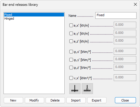
Names of saved releases
On the left hand side is a scrollable list shows every saved release set.
Click a name to load its parameters into the right-hand controls.
Parameters
On the right hand side are the parameters for selected release.
- Name – text field for the selected release set
- Degrees of freedom – tick a box to activate the numeric spring field
- e,x′ – axial translation
- e,y′ – local y translation
- e,z′ – local z translation
- φ,x′ – torsion
- φ,y′ – bending about y
- φ,z′ – bending about z
- v,x' – torsional warping
- Quick presets
- Fixed – sets every spring to rigid
- Hinged – releases rotations φ,y′, φ,z′ and warping v,x', while keeping others rigid
Bottom-row actions
- New – add the current settings as a new library entry
- Modify – overwrite the highlighted entry with current settings
- Delete – remove the highlighted entry
- Import – load a .fdlbc file to add entries. Entries with matching names will be ignored, keeping the local definitions
- Export – save the entire library to an external file