Physical alignment
The Physical alignment dialogue lets you fine-tune how an element’s physical shape is positioned relative to the analytical line within its cross-section.
Following tools use this dialogue:
- Beam
- Column
- Truss member
- Wall foundation
- Intermediate section
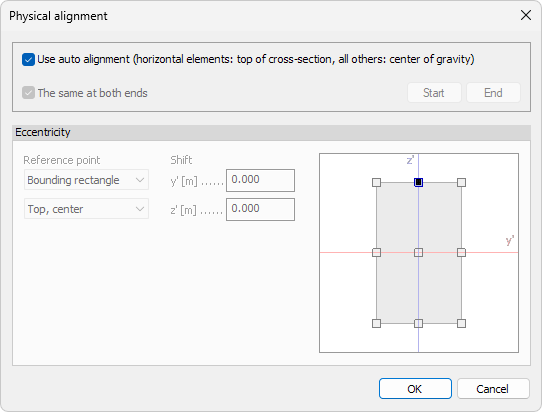
When you press the Physical alignment tool, the following window opens.
General options
- Use auto alignment – applies the program’s default rules
- Top of cross-section for horizontal members (beams, trusses)
- Centre of gravity for all other members
- The same at both ends – when ticked, start and end share the same alignment.
Untick to assign different offsets at each end.
End-specific settings
When The same at both ends is unticked, two buttons become active:
- Start – edit alignment at the element’s start node
- End – edit alignment at the element’s end node
Select a button to make it current, then enter offsets below.
Eccentricity
Specify local offsets between the analytical line and the physical centroid.
Reference point
There are two drop-down menus for selecting where the offset shifts are measured from:
- Base point – select the base for the measurements. Available options are: Center of gravity, Shear center and Bounding rectangle
- Point on bounding rectangle – only available when Bounding rectangle is selected as the Base point. Select one of the nine reference points on the bounding rectangle as the base
Shift
The Shift values contain the offsets from the selected reference point.
- y′ – lateral offset
- z′ – vertical offset
Graphical snap
A miniature cross-section sketch shows key reference points (e.g., top-left corner, centroid). Click any point to auto-fill the y′ and z′ fields with its coordinates, ensuring quick and accurate placement.
If Bounding rectangle is selected as the reference point, then the graphical snapping window allows to change the Point on bounding rectangle, but does not change the Shift offset values.