Design tabs in general
Design tabs in general
Design tabs contains tools for running design analysis, add details related to the design and work with design results.
All design tabs have the same structure, with similar panels and tools. Below is an example of the Concrete design tab, where the main panels and tools are visible.

The structure of the design tabs is explained in more detail in the sections below. In general, the design tabs have the following main panels and tools:
- Design calculations – tools for running design analysis and checks
- Design results – tools for displaying and managing design results
- Design configuration – tools for setting up design configuration before running the design analysis
- Design subtype selector – drop-down menu for selecting the design subtype, which controls the available tools for design detailing
- Additional design tools – various tools for adding design related details or parameters to the elements, such as buckling lengths, shear control zones and steel bar stiffeners
- Design calculation parameters – tool for setting up the design calculation parameters for selected elements
- Design groups – tool for creating and managing design groups
- Auto and manual design – tools for automatically or manually adding design detailing to the elements based on the most optimal utilization of the elements or user input and preferences
- Copy applied quantity – tool for copying the applied design detailing quantity from one element to another
- Design check – tool for checking the design utilization and design checks of the elements after the design detailing of the element
- Applied quantity – tools for applying and removing design detailing quantity. The design detailing quantity is the added quantity of the design elements, such as reinforcement bars, shear links, steel beam sections etc.
Design calculations
To see the design results and work with the detailing tools, the design analysis must be run first. The design analysis can be run through the Calculate tool on the Calculate panel on any of the design tabs.

The tool opens a Calculations dialogue where the design analysis can be set up and run. This dialogue is the same as the one used for analysis calculations, but with the added Design calculations option.
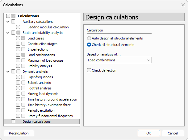
The Design calculations options are:
-
Auto design all structural elements – runs the automatic detailing and design checks for all structural elements in the model. This option will overwrite any existing detailing and design according to the most optimal utilization of the elements.
-
Check all structural elements – runs the design check for all structural elements in the model. This option is used to check the utilization and design checks of already detailed elements.
-
Based on analysis of... – drop-down menu to select whether the design is based on Load combinations or Load groups results.
-
Check deflection – runs the deflection check for all suitable elements in the model. This option is used to check the utilization of the deflection of already detailed elements.
To read more about analysis calculation options, see the topic:
User interface ➔ Tab menus ➔ Analysis ➔ Calculate
Design results display
The design results can be shown after the relevant design analysis is run. The display, visualization, and management of design results are controlled through the various panels and tools available in the design tabs.

There are 3 panels on the design tabs for working with the results:
- Manage results – tools for storing, loading and organising result sets
- Quick change – quick access to common result display settings
- Auxiliary result objects – tools for result points, result lines and virtual bars
The tools for displaying and managing design results are equivalent to the tools for analysis results. To see the analysis results tools, see the relevant topics below.
For Manage results panel, see:
User interface ➔ Tab menus ➔ Analysis ➔ Panel Manage results
For Quick change panel, see:
User interface ➔ Tab menus ➔ Analysis ➔ Panel Quick change
For Auxiliary result objects panel, see:
User interface ➔ Tab menus ➔ Analysis ➔ Panel Auxiliary result objects
Design configuration
Some design tabs have a Design configuration panel with one Configure tool for setting up the design configuration.
![]()
The tool opens a new dialogue where relevant design settings can be set before running the design calculations. The settings in the dialogue are specific to the design type of the tab.
Design subtype selector
Some design tabs have a design subtype selector – a drop-down menu for selecting the design subtype. The design subtype is a specific type of element within the design type of the tab.

For example, the Concrete tab subtypes on the image above are:
- Bar reinforcement and section
- Shell reinforcement: longitudinal
- Shell reinforcement: shear
- Punching reinforcement
- Concealed bar reinforcement
All the design tools are adjusted to the selected design subtype and some of the tools may be available for only certain subtypes.
The design calculations are run for all the subtypes, regardless of the selected subtype. The subtype selector only controls the tools available for the design detailing.
Additional design tools
The design tabs have various tools for adding design related details or parameters to the elements, such as buckling lengths, shear control zones and steel bar stiffeners. The tools are specific to the design type of the tab.

For example, the Concrete tab Bar reinforcement and section subtype has the following additional design tools:
- Buckling length
- Reduction zone
Design calculation parameters
All design tabs have a Design calculation parameters tool for setting up the design calculation parameters for selected elements.

In the design calculation parameters you can set up parameters, such as the applied design code check paragraphs, 2nd order effects, eccentricities and buckling curves used in the design code, fire duration and parameters, etc. These parameters are used in the design checks and affect the utilization of the elements. The parameters are specific to the design type of the tab.
Design groups
All design tabs have a Design group tool for creating and managing design groups.

Design groups are used for grouping elements for design and result management purposes. The design groups can be used to design all the elements in one group with the same detailing, by using the highest utilized element in that group.
The Design group tool opens a Design group tool palette:

Main tools
- Define – create a new design group or modify an existing one
- Properties – check or edit parameters of an existing group. Opens the Default settings dialogue for the selected group
- Add members – add elements to the design group
- Remove members – remove elements from the design group
- Explode – remove the design group but keep the elements in the model
- Create User defined filter – create a user-defined filter based on the design group members. The filter can be used for filtering the elements in the model and results
- Default settings – set default parameters for the design group (read below in more detail)
Additional setting
- Name – name of the design group
- Colour – colour of the design group, used for visualisation of the group members in the model
Default settings
When you press the Default settings button, a dialogue window opens.

- Name – name of the design group
- Colour – colour of the design group, used for visualisation of the group members in the model
Auto and manual design
All design tabs have tools for both auto and manual design.

The Auto design is used to automatically add design detailing to the elements based on the most optimal utilization of the elements. The Manual design is used to add design detailing to the elements based on the user input and preferences.
Both auto and manual design tools have their own dialogues and options that are specific to the design type of the tab and selected subtype.
The tools can be used consecutively for the same element, but with different settings and preferences. For example, the Auto design tool can be used to automatically add reinforcement bars to a concrete beam based on the most optimal utilization, while the Manual design tool can be used to further refine the reinforcement to the same beam based on the user input and preferences.
Copy applied quantity
All design tabs have a Copy applied quantity tool for copying the applied design detailing quantity from one element to another.

The tool has no additional dialogue and works directly in the model. To use the tool, first select the tool, then select the element with the design detailing quantity that you want to copy from, and then select the element(s) that you want to apply the copied quantity to.
Only the quantity of the design detailing is copied, not the design parameters or settings. For example, if you copy the applied quantity of reinforcement bars from one concrete beam to another, only the number and size of the bars will be copied, but not the design parameters such as the design code check paragraphs or fire duration.
You need to run the design check after using the tool to see the effect of the copied quantity on the design results.
Design check
Every design tab has a Check tool in the relevant design panel. The tool is used for checking the design utilization of the elements and check the design analysis for the selected element after the design detailing of the element.
![]()
The Check tool opens a design Check tool palette and Utilization table, with the design check results for the selected element. The design check dialogue is specific to the design type of the tab.
The tool does not run the design analysis (for example, it does not find internal forces or design forces), so the design results must be available before using the tool. To run the design analysis, use the Calculate tool as described in the previous section.
Applied quantity
Every design tab has an Applied quantity panel with tools for applying and removing design detailing quantity. The design detailing quantity is the added quantity of the design elements, such as reinforcement bars, shear links, steel beam sections etc.

The panel has the following tools:
- Delete all applied quantity – deletes all applied design detailing quantity of the selected element (for example, all added reinforcement on a concrete beam).
- Apply design changes and recalculate – applies the added design detailing changes and recalculates the design analysis for all elements.