Auto design
Auto design
Use Auto design to define design preferences and run automatic composite design for the selected subtype.

Tool palette
When you activate Auto design, a tool palette opens.

The tool palette contains the following main tools and options:
-
Parameters – opens a subtype-specific parameters dialogue after you select an element in model view
-
Design – runs automatic design with the selected settings
-
Calculation – lets you choose:
- Load combinations
- Load groups
-
Display table – checkbox that shows the utilization table
Parameters dialogue
When you select an element in model view, the Parameters dialogue opens based on the currently selected design subtype.
Composite column subtype
The dialogue opens with two tabs: Cross-section and Reinforcement.
Cross-section tab
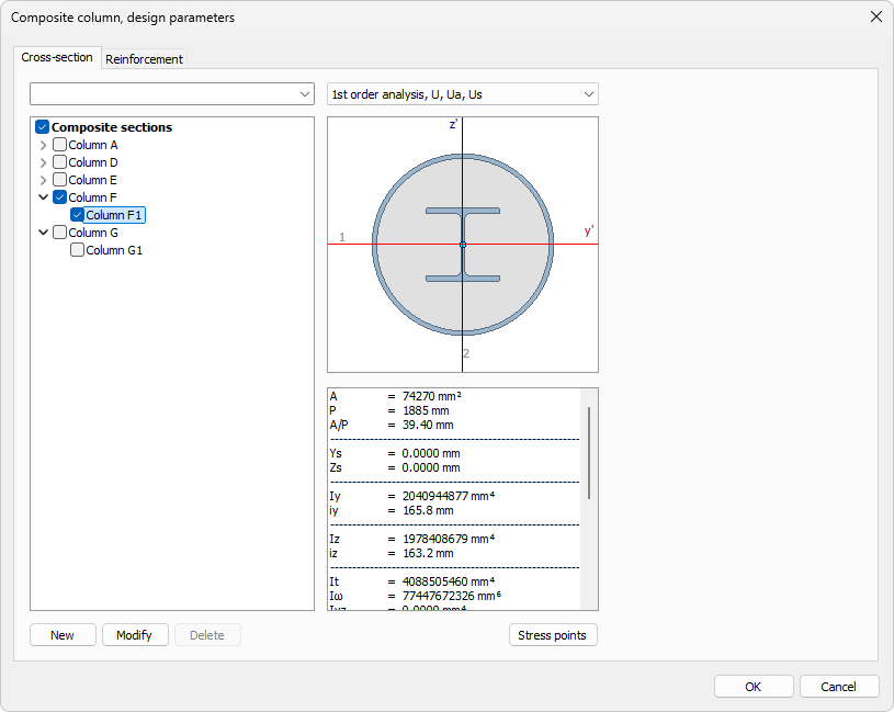
Use this tab to define which composite section types and sizes are allowed during auto design.
-
Section type tree (left side) – lists the available composite section types (e.g. Column A, Column D, Column E, Column F, Column G). Expand a type to see its predefined sizes
-
Checkboxes – mark a section type or an individual size to include it as an allowed candidate for auto design
-
Top drop-down menus – filter the section list, and choose the analysis method (e.g. 1st order analysis, U, Ua, Us)
-
Section preview and data (right side) – shows the section shape, local axes, stress point markers, and the main section parameters for the currently selected item
-
New, Modify, Delete – create a new composite section, modify, or delete the selected one
-
Stress points – opens the stress points dialogue for the selected section
Reinforcement tab
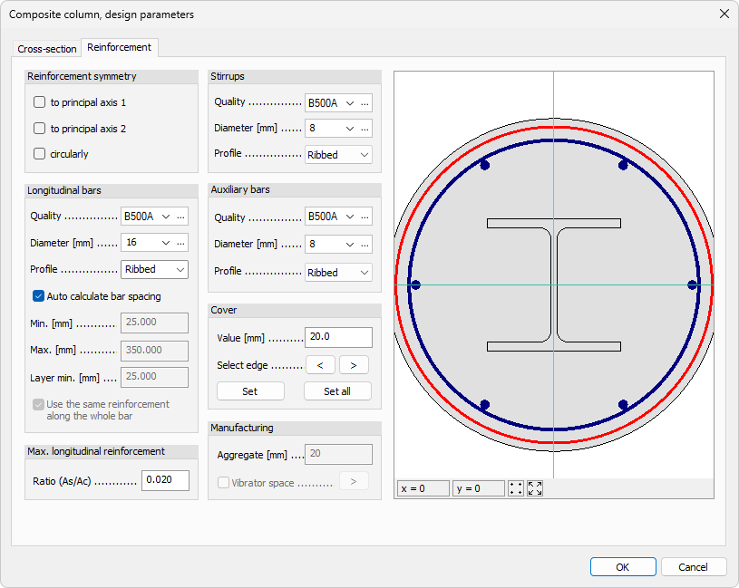
Use this tab to define the reinforcement detailing applied to the section selected on the Cross-section tab. The tab is divided into groups for symmetry, bars, steel options, cover, and manufacturing constraints.
Reinforcement symmetry
-
to principal axis 1 – apply symmetry relative to principal axis 1
-
to principal axis 2 – apply symmetry relative to principal axis 2
-
circularly – apply circular reinforcement symmetry
Longitudinal bars
-
Quality – drop-down list with available reinforcing steel materials from the library
-
Diameter – drop-down list with available bar diameters
-
Profile – choose bar profile type:
- Smooth
- Ribbed
-
Auto calculate bar spacing – checkbox for automatic spacing calculation
-
Min. – manual minimum spacing, available when automatic spacing is disabled
-
Max. – manual maximum spacing, available when automatic spacing is disabled
-
Layer min. – manual minimum clear distance between bar layers, available when automatic spacing is disabled
-
Use the same reinforcement along the whole bar – keep one reinforcement arrangement along the full bar length
Max. longitudinal reinforcement
- Ratio (As/Ac) – numeric field for the maximum reinforcement ratio between concrete and steel
Stirrups
-
Quality – drop-down list for steel quality selection
-
Diameter – drop-down list for steel diameter selection
-
Profile – choose bar profile type:
- Smooth
- Ribbed
Auxiliary bars
-
Quality – drop-down list for steel quality selection
-
Diameter – drop-down list for steel diameter selection
-
Profile – choose bar profile type:
- Smooth
- Ribbed
Cover
-
Value – numeric field for concrete cover
-
Select edge – cycle through edges using the arrow buttons to review or set edge-specific cover values
-
Set – apply the current cover value to the currently selected edge
-
Set all – apply the current cover value to all edges
Manufacturing
-
Aggregate – numeric field for aggregate size
-
Vibrator space – checkbox that enables vibrator space handling
The right side of this tab shows the section preview, including the reinforcement layout, cover lines, and bar positions.
Deltabeam subtype
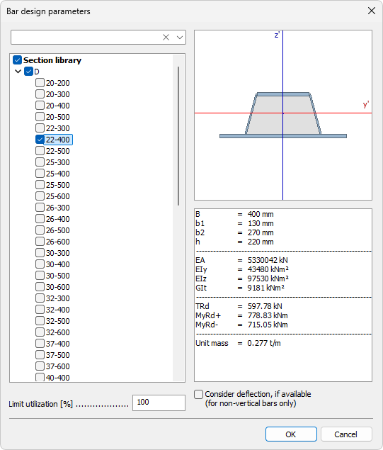
The dialogue opens with a section selection where you choose allowed sections to be used in auto design.
-
Section library (left side) – browse and filter available Deltabeam sections using the regular search function, and mark checkboxes in front of sizes to include them as allowed options
-
Section preview and data (right side) – review section shape and the main section parameters for the currently selected item
Additional options in this subtype:
-
Limit utilization – numeric field that allows using a target limit lower than 100%
-
Consider deflection, if available (for non-vertical bars only) – checkbox to include deflection result check in design
Design tool
Use Design to select suitable elements in model view and run automatic design with current settings.
When Display table is checked a Utilization table opens.
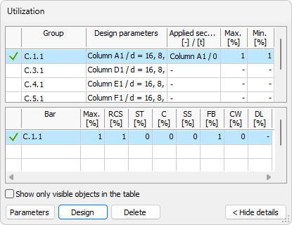
The table allows you to review utilization and update selected manual design quantities.
To read more about utilization table, see the Check tool article:
User interface ➔ Tab menus ➔ Composite design ➔ Check
Table options and buttons
The bottom part always contains:
-
Show only visible objects in the table – limits rows to currently visible model objects
-
Parameters – opens the Default settings dialogue for selected row
-
Design – runs design for selected row
-
Delete – deletes applied design quantity for selected row