Calculation parameters
Calculation parameters
Calculation parameters tool is used to set the design and verification parameters for timber elements.
![]()
When you select the tool then you need to select the element for which you want to set the design parameters. After selecting the element, the calculation parameters dialogue will open. The dialog depends on the selected subtype of design and contains different parameters for different subtypes.
Parameters for timber bar

General settings
-
Maximal distance between calculated sections – sets the largest spacing between evaluation sections along the bar, which controls how detailed the design check is along its length.
-
Second-order analysis handling – lets you decide how second-order effects are included in design:
-
Ignore 2nd order analysis – uses first-order effects only.
-
Consider 2nd order analysis, if available – uses second-order results when they exist, otherwise first-order results.
-
2nd order internal forces + 1st order design – uses second-order internal forces but keeps first-order design format checks.
-
Lamination
- Lamination thickness – defines the thickness of individual laminations used in the timber member, which affects the design checks that depend on lamella geometry.
Parameters for orthotropic panel

-
Reduction factor of material properties – applies a reduction to orthotropic panel material properties used in verification, for example to account for design assumptions or model uncertainty.
-
β c – sets the coefficient used in the panel resistance/check formulas for the selected design model.
Parameters for CLT panel

Checking options
-
Shear interaction formulas – enables interaction checks between shear effects according to the selected timber design method.
-
Torsional check – enables or disables torsional verification in the automatic design checks.
-
Plank width – defines the effective plank width used in CLT panel resistance and stability calculations.
Buckling options
-
Reduction factor of material properties – scales down CLT material properties used in buckling-related verification.
-
β c – sets the buckling-related coefficient used in the CLT design check formulas.
Parameters for timber bar, fire design
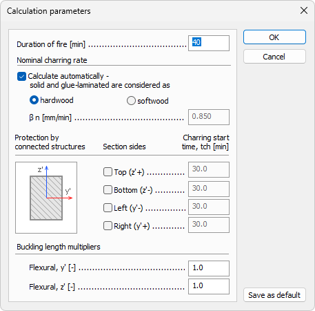
- Duration of fire – defines the fire exposure time used to calculate charring depth and reduced section capacity.
Nominal charring rate
-
Calculate automatically – lets the program determine nominal charring rates from the selected timber type.
-
Timber type selection (hardwood/softwood) – when automatic mode is active, this choice sets the charring-rate basis for both solid and glue-laminated timber.
-
β n – when automatic mode is off, you enter the nominal charring rate manually.
Protection by connected structures
-
Section sides – selects which sides are protected by connected structures, reducing direct fire exposure for those faces.
-
Charring start time – sets a delay before charring starts on each selected protected side.
Buckling length multipliers
-
Flexural, y' – sets the effective buckling-length multiplier for bending about the local y' axis in fire design.
-
Flexural, z' – sets the effective buckling-length multiplier for bending about the local z' axis in fire design.
Parameters for CLT panel, fire design
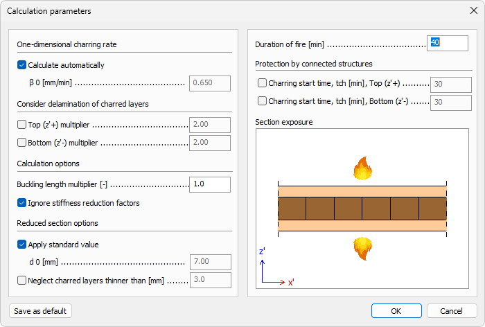
One-dimensional charring rate
-
Calculate automatically – lets the program assign the one-dimensional charring rate from standard assumptions.
-
β0 – when needed, lets you define the one-dimensional charring rate used in the CLT fire check.
Consider delamination of charred layers
-
Top (z′+) multiplier – enables delamination influence for the top face and sets its multiplier value.
-
Bottom (z′-) multiplier – enables delamination influence for the bottom face and sets its multiplier value.
Calculation options
-
Buckling length multiplier – defines the effective buckling length factor used in the CLT fire stability check.
-
Ignore stiffness reduction factors – excludes stiffness-reduction factors from the fire calculation when enabled.
Reduced section options
-
Apply standard value – uses the code-standard default value for the reduced-section parameter instead of a custom value.
-
d0 – sets the zero-strength layer thickness used to form the effective residual section in fire design.
-
Neglect charred layers thinner than – ignores very thin charred layers below the specified limit in reduced-section evaluation.
Fire duration
- Duration of fire – defines the fire exposure time for CLT fire verification and section reduction.
Protection by connected structures
-
Charring start time, tch [min], Top (z′+) – enables and sets the delayed charring start on the top face due to protection.
-
Charring start time, tch [min], Bottom (z′-) – enables and sets the delayed charring start on the bottom face due to protection.
Section exposure
- Section exposure – lets you graphically define which section faces are exposed to fire, which drives the charring and reduced-section calculation.