Calculation parameters
Calculation parameters
Calculation parameters tool is used to set the design and verification parameters for steel elements.
![]()
When you select the tool then you need to select the element for which you want to set the design parameters. After selecting the element, the calculation parameters dialogue will open. The dialog depends on the selected subtype of design and contains different parameters for different subtypes.
Parameters for bar elements
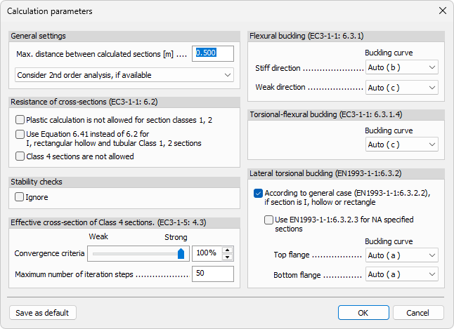
General settings
-
Max. distance between calculated sections – numeric field for the maximum spacing between design sections along bars.
-
2nd order result handling – drop-down menu with three options:
-
Ignore 2nd order analysis
-
Consider 2nd order analysis, if available
-
2nd order internal forces + 1st order design
-
Resistance of cross-sections (EC3-1-1: 6.2)
-
Plastic calculation is not allowed for section classes 1, 2 – checkbox to disable plastic resistance checks for Class 1 and Class 2 sections.
-
Use Equation 6.41 instead of 6.2 for I, rectangular hollow and tubular Class 1, 2 sections – checkbox to switch to Equation 6.41 for the listed section types and classes.
-
Class 4 sections are not allowed – checkbox to exclude Class 4 sections from design verification.
Stability checks
- Ignore – checkbox to ignore stability checks for steel bars.
Effective cross-section of Class 4 sections (EC3-1-5: 4.3)
-
Convergence criteria – slider with an adjacent numeric field for setting the convergence percentage.
-
Maximum number of iteration steps – numeric field for iteration limit.
Flexural buckling (EC3-1-1: 6.3.1)
-
Stiff direction - Buckling curve – drop-down menu for selecting the buckling curve in stiff direction.
-
Weak direction - Buckling curve – drop-down menu for selecting the buckling curve in weak direction.
Torsional-flexural buckling (EC3-1-1: 6.3.1.4)
- Buckling curve – drop-down menu for selecting the torsional-flexural buckling curve.
Lateral torsional buckling (EN1993-1-1: 6.3.2)
-
According to general case (EN1993-1-1: 6.3.2.2), if section is I, hollow or rectangle – checkbox to activate general-case LTB for these section types.
-
Use EN1993-1-1: 6.3.2.3 for NA specified sections – checkbox to use the NA-specific method for relevant sections.
-
Top flange - Buckling curve – drop-down menu for selecting LTB buckling curve of top flange.
-
Bottom flange - Buckling curve – drop-down menu for selecting LTB buckling curve of bottom flange.
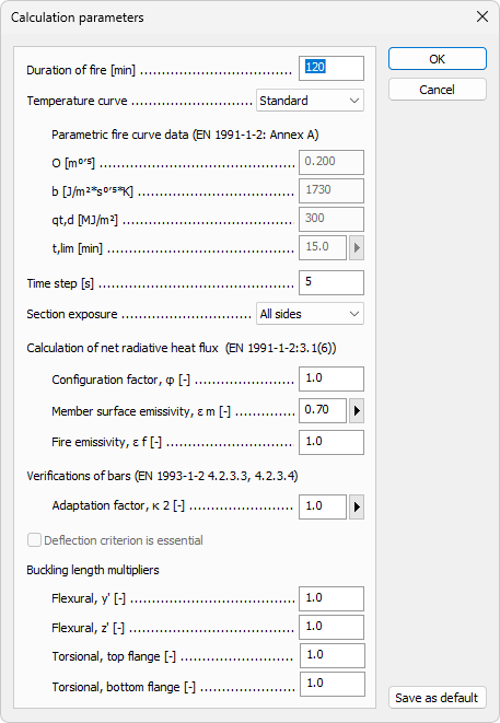
Parameters for fire design
-
Duration of fire – numeric field.
-
Temperature curve – drop-down menu with:
- Standard
- External
- Hydrocarbon
- Parametric
Parametric fire curve data (EN 1991-1-2: Annex A)
This group is available when Parametric is selected in Temperature curve.
-
O – numeric field.
-
b – numeric field.
-
qt,d – numeric field.
-
t,lim – numeric field with an additional button that opens a small predefined-times table:
- Slow fire growth rate
- Medium fire growth rate
- Fast fire growth rate
Parameters for fire exposure
-
Time step – numeric field.
-
Section exposure – drop-down menu with:
- All sides
- Three sides
- Flange only
Calculation of net radiative heat flux (EN 1991-1-2: 3.1(6))
-
Configuration factor, phi – numeric field.
-
Member surface emissivity, em – numeric field with an additional button that opens a small predefined-options table:
- Carbon steel
- Stainless steel
-
Fire emissivity, ef – numeric field.
Verifications of bars (EN 1993-1-2: 4.2.3.3, 4.2.3.4)
- Adaptation factor, kappa2 – numeric field with an additional button that opens a small predefined-values table:
- At the supports of statically indeterminate beam
- Otherwise
Deflection checks
- Deflection criterion is essential – checkbox.
Buckling length multipliers
-
Flexural, y' – numeric field.
-
Flexural, z' – numeric field.
-
Torsional, top flange – numeric field.
-
Torsional, bottom flange – numeric field.