Auto design
Auto design
Use Auto design to define design preferences and run automatic steel design for the selected design subtype.
The workflow is common for multiple steel subtypes, with some subtype-specific parameter dialogues.

Auto design is not available for subtype Steel joint.
Tool palette
When you activate Auto design, a tool palette opens.

The tool palette contains the following main tools and options:
-
Parameters – opens a subtype-specific parameters dialogue after you select an element in model view.
-
Design – runs automatic design with the selected settings.
-
Calculation – lets you choose:
- Load combinations
- Load groups
-
Display table – checkbox that shows the utilization table.
Parameters dialogue
When you select an element in model view, the Parameters dialogue opens based on the currently selected design subtype.
Steel bar subtype
The dialogue opens with section selection where you choose allowed sections to be used in auto design.
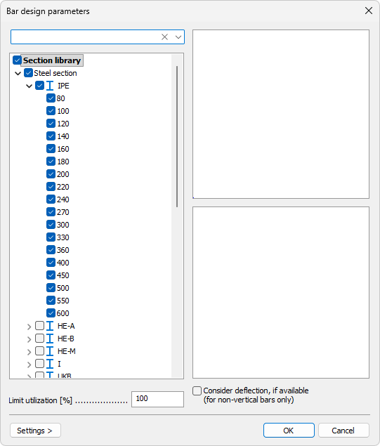
This selection is similar to the Bar Section dialogue.
To read more about section selection logic, see:
User interface ➔ Tab menus ➔ Structure ➔ Additional dialogues ➔ Bar Section
Additional options in this subtype:
-
Limit utilization – numeric field that allows using a target limit lower than 100%.
-
Consider deflection, if available (for non-vertical bars only) – checkbox to include deflection result check in design.
Steel bar, shell model subtype
The dialogue contains a list of possible shell thicknesses.

Each thickness has a checkbox so you can include or exclude it from the auto design candidates.
Steel bar, fire design subtype

The dialogue has two main options:
-
Design fire protection material
-
Calculate maximum temperature
When Design fire protection material is selected, these parameters are available:
-
Material – drop-down menu with an Edit library button. Shows all fire protection materials from the library.
-
Minimum thickness – numeric field.
-
Maximum thickness – numeric field.
-
Thickness increment – numeric field.
The Edit library button opens the Fire protection material library dialogue.
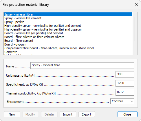
In this dialogue:
-
Top part shows the material list.
-
Middle part contains parameters: Name, Unit mass, Specific heat, Thermal conductivity, and Encasement.
-
Encasement is a drop-down with two options: Contour and Hollow.
-
Bottom part contains buttons: New, Modify, Delete, Import, Export.
When Calculate maximum temperature is selected, one parameter is available:
- Temperature step – numeric field.
Regardless of selected radio option, there is one common parameter at the bottom:
- Limit utilization – numeric field for utilization target.
Design tool
Use Design to select suitable elements in model view and run automatic design with current settings.
When Display table is checked a Utilization table opens.
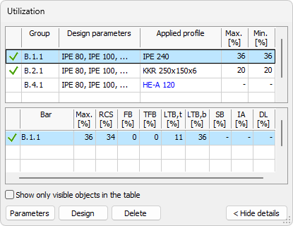
The table allows you to review utilization and update selected manual design quantities.
To read more about utilization table, see the Check tool article:
User interface ➔ Tab menus ➔ Steel design ➔ Check
Table options and buttons
The bottom part always contains:
-
Show only visible objects in the table – limits rows to currently visible model objects.
-
Parameters – opens the Default settings dialogue for selected row.
-
Design – runs design for selected row.
-
Delete – deletes applied design quantity for selected row.