Shell reinforcement: longitudinal
When Shell reinforcement: longitudinal is selected in the subtype selector, the Auto design tool palette is used to define reinforcement layouts for shell faces before running the design.
Tool palette

The Auto design tool palette contains the following tools and options:
-
Parameters – select a suitable shell object and open the reinforcement parameter dialogue.
-
Design – run automatic longitudinal shell reinforcement design with the current settings.

-
Calculation – only while Design is selected, lets you choose Load combinations or Load groups as the design basis.
-
Display table – checkbox that shows the utilization table when enabled.
-
Delete options – checkboxes that define which existing reinforcement meshes are deleted during design run:
- Manual
- Auto - base net
- Auto - additional
- Auto - crack width
-
Colour settings – opens a dialogue where you define display colors for reinforcement layers and directions. Read below in more detail.
Parameters dialogue
After you start Parameters, you can select between two options on the tool palette:
-
Double layer reinforcement – uses separate reinforcement tabs for Bottom face and Top face.
-
Single layer reinforcement – uses one reinforcement tab for the middle reinforcement layer only.
After selection one of the options, you are prompted to select a suitable shell object which opens the reinforcement parameter dialogue window.
Reinforcement parameters for shells
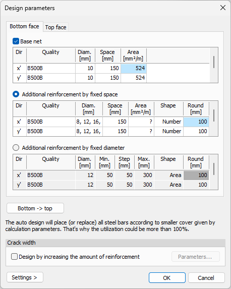
The dialogue for shell reinforcement parameters is structured in tabs for the Bottom face and Top face when Double layer reinforcement is selected, or a Mid plane tab for when Single layer reinforcement is selected.
Each reinforcement layer tab contains settings for base net reinforcement, additional reinforcement, and iterative crack-width based design refinement.
Base net
- Base net – checkbox that enables a base reinforcement net for the whole plate.
The Base net table contains rows for x' and y' directions with the following columns:
-
Dir – reinforcement direction row for x' or y'.
-
Quality – drop-down list for reinforcement steel quality.
-
Quality library button (...) – open the steel quality library.
-
Diameter – drop-down list for reinforcement bar diameter.
-
Diameter library button (...) – open the diameter library.
-
Space – drop-down list for bar spacing.
-
Area – automatically calculated reinforcement area value.
Additional reinforcement mode
Below or next to the base net settings, you choose one of two additional reinforcement methods. Only one method can be active at a time.
-
Additional reinforcement by fixed spacing – define extra reinforcement using selected diameters and fixed spacing values.
-
Additional reinforcement by fixed diameter – define extra reinforcement using a fixed diameter and variable spacing limits.
Additional reinforcement by fixed spacing
The table for Additional reinforcement by fixed spacing contains the following columns and settings:
-
Dir – reinforcement direction.
-
Quality – drop-down list for reinforcement steel quality.
-
Quality library button (...) – open the steel quality library.
-
Diam. – opens a small dialogue listing available diameters, where you select one or more suitable values by checkbox.
-
Space – drop-down list for bar spacing.
-
Area – automatically calculated reinforcement area value.
-
Shape – opens a small dialogue where the reinforcement distribution shape is selected.
-
Round – numeric field for reinforcement length rounding.
The Shape dialogue contains the following options:
-
Minimum number of rectangles – minimizes the number of reinforcement rectangles.
-
Minimum area of rectangles – minimizes the reinforcement rectangle area.
-
Stepped – applies stepped rectangle spacing.
Additional fields in the Shape dialogue depend on the selected method:
-
b min – numeric field for the minimum area width, available for Minimum area of rectangles.
-
s – numeric field for the step length, available for Stepped.
Additional reinforcement by fixed diameter
The table for Additional reinforcement by fixed diameter contains the following columns and settings:
-
Dir – reinforcement direction.
-
Quality – drop-down list for reinforcement steel quality.
-
Quality library button (...) – open the steel quality library.
-
Diam. – drop-down list for reinforcement diameter.
-
Diameter library button (...) – open the diameter library.
-
Min. – numeric field for the minimum spacing between bars.
-
Step – numeric field for the spacing increment.
-
Max. – numeric field for the maximum spacing between bars.
-
Shape – opens a small dialogue where the reinforcement distribution shape is selected.
-
Round – numeric field for reinforcement length rounding.
The Shape dialogue contains the following options:
-
Minimum number of rectangles – minimizes the number of reinforcement rectangles.
-
Minimum area of rectangles – minimizes the reinforcement rectangle area.
-
Stepped – applies stepped rectangle spacing.
Additional fields in the Shape dialogue depend on the selected method:
-
b min – numeric field for minimum band width, available for Minimum area of rectangles.
-
s – numeric field for the spacing step, available for Stepped.
Copy between faces
- Bottom - > Top – button below the tables that copies the current face settings to the opposite face, depending on the active tab.
Crack width
-
Design by increasing amount of reinforcement – checkbox that iteratively increases reinforcement where crack limits are exceeded.
-
Parameters – button available when the checkbox is enabled; opens a dialogue for iteration control settings.
In the Parameters dialogue for iterative increase, you can define:
-
Convergence rate – numeric field for the convergence target used during iteration.
-
Maximum allowed iteration number – numeric field for the iteration limit.
Settings
At the bottom of the design parameters dialogue, the Settings button provides the following functions:
-
Save – save the current parameter setup.
-
Load – load a previously saved parameter setup.
-
Save as default – save the current setup as the default.
-
Load default values – restore the default settings.
Color options

In the shell Design workflow, Colour settings option is available in the tool palette. It opens a dialogue where you define display colors for reinforcement layers and directions (for example, bottom layer base net in x' direction).
Design tool
Use Design to select suitable shell objects in the model view and design them with the current shell reinforcement parameters. You can also open the utilization table and run design from there, similarly to the bar reinforcement workflow.
When Display table is checked and you start Design, a Utilization table opens.
Utilization table structure
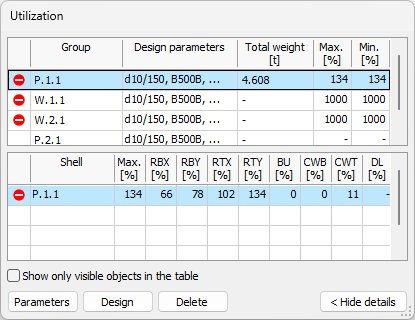
The Utilization table is split into two tables:
-
Groups table (top) – shows design groups and ungrouped single elements.
-
Element details table (bottom) – shows detailed utilization results for elements in the selected group, or for the selected ungrouped single element.
Groups table columns
The groups table uses the same columns as in bar auto design:
-
Passed – unnamed status column that shows if design has been run and what the result is.
-
Group name – group name, or the element name when the row is an ungrouped single element.
-
Design parameters – short overview of the selected design parameters for the group or element.
-
Applied section/Total weight – applied section together with total weight.
-
Max – maximum utilization within the group.
-
Min – minimum utilization within the group.
Element details table columns
The shell element details table contains the following columns:
-
Passed – unnamed status column with pass/fail icon result.
-
Element name – name of the element.
-
Max. – maximum utilization value for the element.
-
RBX – reinforcement utilization for bottom or mid layer in x' or r direction.
-
RBY – reinforcement utilization for bottom or mid layer in y' or t direction.
-
RTX – reinforcement utilization for top layer in x' or r direction.
-
RTY – reinforcement utilization for top layer in y' or t direction.
-
BU – shell buckling utilization.
-
CWB – crack width utilization for bottom face.
-
CWT – crack width utilization for top face.
-
DL – deflection utilization.
Table options and buttons
Below the element details table, the following controls are available:
-
Show only visible objects in the table – limits table rows to currently visible objects.
-
Parameters – opens the same Parameters dialogue as in the tool palette, for the selected group or element.
-
Design – runs design for the selected element in the table.
-
Delete – deletes the added quantity from the selected element.