Shell longitudinal and transverse reinforcement
Use this tool to draw a region for a rebar set or to place a single rebar bar in shell elements.
You can only draw on the currently selected reinforcement layer.
To read more about reinforcement layers, see topic:
User interface ➔ Tab menus ➔ Concrete Design ➔ Reinforcement Layers
Tool palette
Manual design opens a tool palette where you define how reinforcement is created and applied.

Main tools
-
Define – select the reinforcement definition type and drawing method.
-
Properties – set reinforcement parameters for the selected method. Opens Default settings for the selected reinforcement set or bar
-
Anchorage – configure anchorage-related settings for the drawn reinforcement
-
Default settings – set default values for the active definition function (read below in more detail)
Definition functions
Use the following functions to create reinforcement:
-
Straight – draw regular straight bars in sets.
-
Centric – draw centrically arranged rebar sets.
-
Single – draw individual rebars.
Area definition methods for Straight and Centric
For Straight and Centric reinforcement, you can define the region with:
-
Rectangular – define a rectangular reinforcement area.
-
Circular – define a circular reinforcement area.
-
Polygonal – define a polygon-shaped reinforcement area.
-
Pick lines – define the area by selecting existing lines.
-
Pick existing region – reuse an already defined region.
Additional functions for Single
The Single function includes two dedicated placement modes:
-
By line – place one or more single bars along a defined line.
-
By rectangle – place one or more single bars in a rectangular layout.
For By line, line definition methods are:
-
By end points – define the bar line by selecting start and end points.
-
By shell edge – define the bar line along a shell edge.
-
By shell corner – define bar placement from a shell corner.
Additional settings
The available fields depend on the selected definition method.
-
Diameter – select bar diameter from a dropdown, with Edit library support.
-
Space – enter bar spacing as a numeric value.
-
Cover – enter concrete cover as a numeric value.
-
Required area – show the required reinforcement area from analysis results.
-
Applied area – show the applied reinforcement area as a read-only value.
-
Apply on both sides – apply the drawn mesh on both top and bottom sides.
-
Angle – set reinforcement angle, used for centric reinforcement.
-
Number of bars – set how many bars are created in Single mode at the same location.
-
Overhang – set extension length beyond the shell edge in By shell edge mode.
-
Length – set bar length next to the selected corner in By shell corner mode.
Anchorage
Use this tool to set anchorage-related parameters for the drawn reinforcement.

- Automatic (Fully anchored at shell edge, not anchored otherwise) – set the reinforcement set to be fully anchored at shell edges and not anchored elsewhere. This is the default setting for all reinforcement sets.
- Manual – set the reinforcement set to be manually anchored. When you select this option, the following fields become available:
- r – set the required anchorage length as a percentage of the bar length
- Calculate anchorage length automatically – checkbox to calculate the required anchorage length l,bd based on the selected code and bar properties
- l,bd – numeric field to set the required anchorage length l,bd. This field is only editable when Calculate anchorage length automatically is unchecked. The calculated or manually set l,bd is shown as a read-only value in the reinforcement properties after drawing.
Default Settings
Default settings are linked to the active definition function (Straight, Centric, or Single).
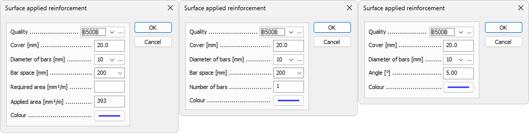
Depending on function, the available options include:
-
Quality – select bar quality from a dropdown, with Edit library support.
-
Cover – set default concrete cover.
-
Diameter of bars – select default bar diameter from a dropdown, with Edit library support.
-
Bar space – set default spacing between bars.
-
Required area – show the required result value for reinforcement area.
-
Applied – show the applied reinforcement area as a read-only value.
-
Colour – open the color palette for the selected rebar set or single bar.
-
Number of bars – set default quantity for single-bar placement operations.
-
Angle – set default reinforcement angle where applicable.