Solid stresses
The Solid stresses analysis result shows stresses in solid finite elements under the current loading or analysis conditions.
It allows you to evaluate the complete stress state within three-dimensional finite elements, including normal and shear stresses as well as principal stress magnitudes and their spatial directions.
Currently, the three-dimensional soil object is the only structural element that makes use of solid finite elements.
Solid stresses are available for several static and dynamic analysis contexts.
- Load cases
- Moving load maximum
- Construction stages
- Load combinations
- Maximum of load combinations
- Maximum of load groups
- Seismic analysis
- Time history, ground acceleration
- Time history, excitation force
- Periodic excitation
Result selection
Depending on the selected analysis context, additional selections are required to display Solid stresses. One or more of the following parameters may need to be selected from the result lists:
- load case type, such as ultimate or quasi-permanent
- load case or load combination
- stress component, for example principal stress or directional stress
- moving load, for moving load–based results
- construction stage
- simultaneous value, for selected maximum-type results
- seismic shape
- time step, for time history results
Only the selections relevant to the active analysis type are shown.
The Simultaneous selection is available for some maximum-type results, such as Maximum of load combinations.
First, select the stress component for which the extreme value is evaluated, for example σ x'+. Then select a Simultaneous component, for example σ x'. The result will display the values for σ x component that correspond to the load combination which generated max σ x'+.
This allows you to study the combined effect of stresses occurring at the same critical positions.
You can see the result for the minimum/maximum stress component itself if you select the Simultaneous value to be the same as the stress component.
For example, select the stress component σ x'+ and then select a Simultaneous component σ x'+. The result will display the result for maximum x' direction stress values in the solid.
Result display
Solid stresses can be displayed using the following result display types:
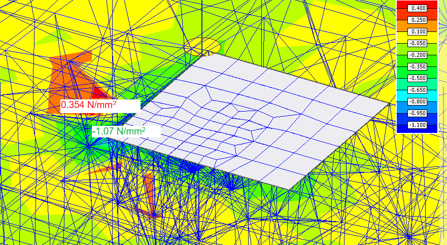
- Colour palette – stresses visualised as coloured fields on solid elements
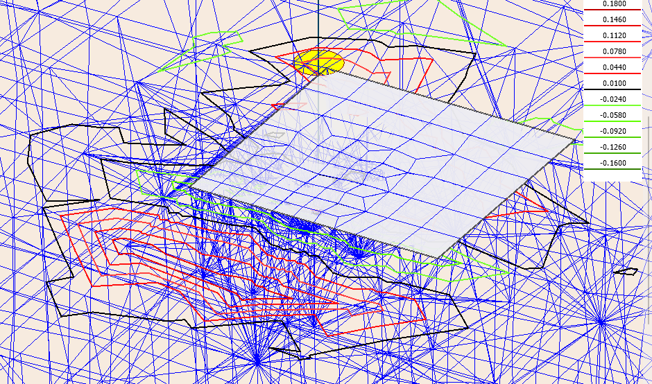
- Contour lines – stresses shown as coloured contour lines on solid elements
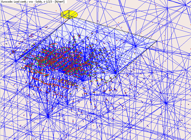
- σ 1/2/3 – a special vector display showing all three principal stresses simultaneously at each finite element, including their magnitudes and directions in space
Colour palette
Stresses visualised as coloured fields on solid elements.
Contour lines
Stresses shown as coloured contour lines on solid elements.
Special display for σ 1/2/3
When the σ 1/2/3 result component is selected, a special vector display is used instead of a colour palette or contour lines.
Three directional arrows are drawn simultaneously at each finite element, one for each principal stress.
Each arrow shows both the magnitude and the spatial direction of the corresponding principal stress, letting you see the full principal stress state at a glance.